diy solar

diy solar

makeSkyBluer

In your schematic, if A8(74HC14-1) is plus, 74HC14-2,3,5 are minus. 74HC14-4 (PWM1) and 74HC14-6 (PWM2) are plus. So effectively, no inversion. I followed the same two buffers in series scheme. But for the fan drive, no series buffers.
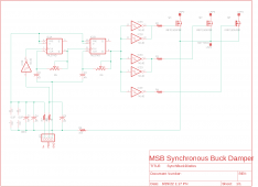
oh... u are RIGHT!! very good.. sorry for the duh..

u might flip fan drv in software if its a problem to add an inverter..
 
I added a bool so easy to flip FAN in software..and also added msb_v113 which u have but is so far the same as PowMr..
 

Attachments

  • makeSkyBluer.zip
    10.4 KB · Views: 5
msb V113
More testing last night.
High side of the NTC still measures correctly at 3.3V.
I added an inverter to the fan drive signal path and the fan on/off now follows the code intent. I am still using your code in post #35.

The msb V113 60A is rated up to 2800 watts for a 48 volts battery. I tried to increase MAX CHARGE WATTS to match it but the maximum is 1000. I do not know what this setting does.

For bench testing, I am using 16 pieces 32700 LifePO4 in series and I set BULK=55.2V and FLOAT=54.4V. I used a 65 volts power supply for PV. I set the voltage gains so the voltage readouts match my testing values. During my testing, the battery voltage exceeded the BULK value and went up to 58 volts. I stopped testing to troubleshoot, but first I need to connect a BMS to my battery pack.
 
Last edited:
msb V113
More testing last night.
High side of the NTC still measures correctly at 3.3V.
I added an inverter to the fan drive signal path and the fan on/off now follows the code intent. I am still using your code in post #35.

The msb V113 60A is rated up to 2800 watts for a 48 volts battery. I tried to increase MAX CHARGE WATTS to match it but the maximum is 1000. I do not know what this setting does.

For bench testing, I am using 16 pieces 32700 LifePO4 in series and I set BULK=55.2V and FLOAT=54.4V. I used a 65 volts power supply for PV. I set the voltage gains so the voltage readouts match my testing values. During my testing, the battery voltage exceeded the BULK value and went up to 58 volts. I stopped testing to troubleshoot, but first I need to connect a BMS to my battery pack.
if u are subbing in a power supply for PV, make sure u have the Neg side connected to PV-.. not battery gnd.. otherwise it will never sense PV current and it might allow voltage to rise like u saw.. just my guess..
I set the max charge limit to 1000 watts..in reality--thats way more than I would recommend u try and run at..these units are way way overated..
in perfect conditions, u might get away with higher wattages successfully, but given normal conditions--high temperature, bad ventilation, etc..it might be prudent to back off trying to run alot of juice.. better to install multiple units..I run 3 msbs.. and my system is small..
 
Power supply negative is connected to PV- and battery negative is separately connected to BT-.

My solar system is 1.6kw PV (16 100 watts panels). The inverter is DIY 3.4kw and currently has only a 1.5 HP pool pump for load 6 hours daily. On a sunny day, with the inverter driving its load, I have tested disconnecting the battery for an hour and the inverter can still drive its load as long as the sun can deliver. The unmodifed msb reads about 1.3kw of PV power, the msb and inverter are in a cabinet with forced air cooling when the inverter heatsink gets hot. I have not tested longer than an hour.
1300w wow.. these msbs are simple Asynch design..meaning there is no active reverse current FET..just a big (to-247) diode to gnd from the inductor to snub the reverse emf..so heat generated becomes a function of amount of power being transformed..user beware..ur forced air cooling appears to be working!!
u can increase the maxChargeWatts limit easily in code--about line 602--
if(dspCURRENT==dspMAXCHARGEWATTS){maxChargeWatts++;
if(maxChargeWatts>1000)maxChargeWatts=1000;}

might want to checkur fire-extinguisher..make sureits ready..
Thanks, the cabinet and battery rack are outside the house, but the fire extinguisher is expired. lol
 
Thanks, the cabinet and battery rack are outside the house, but the fire extinguisher is expired. lol
U might be way ahead to break ur solar system in two..have 2 banks of 800w each..then one msb for each bank..that would be much safer..
 
U might be way ahead to break ur solar system in two..have 2 banks of 800w each..then one msb for each bank..that would be much safer..
Will probably have to do it when I add more loads to my inverter, for now without external monitoring data packet of the msb NTC, will glue thermistor to the msb case to monitor temperature and add to fan control. Will probably change the 3 fans to higher flow rate.

Picture shown was taken in 2018, battery rack was AGM which I converted recently to LifePO4.
 

Attachments

  • cabinet assembly.jpg
    cabinet assembly.jpg
    428.4 KB · Views: 15
Will probably have to do it when I add more loads to my inverter, for now without external monitoring data packet of the msb NTC, will glue thermistor to the msb case to monitor temperature and add to fan control. Will probably change the 3 fans to higher flow rate.

Picture shown was taken in 2018, battery rack was AGM which I converted recently to LifePO4.
awesome!!..looks like that equipment cabinet might be getting little crowded..lol.. suggestion: move the msbs out to their own place..I make these msb 'organizers' out of a 4x8 plywood and a few 2x4s and some scrap wood.. makes 3.. this one is for my son..locations for up to 4 msbs.. each msb has a 16 inch 'chimney' plus--of course-- its own fan..

I working on a small project to make these msbs into synchrounous.. boards coming in soon..might work --if so-- lotta heat wont be anymore..
 

Attachments

  • IMG_20220929_122711.jpg
    IMG_20220929_122711.jpg
    140.4 KB · Views: 15
awesome!!..looks like that equipment cabinet might be getting little crowded..lol.. suggestion: move the msbs out to their own place..I make these msb 'organizers' out of a 4x8 plywood and a few 2x4s and some scrap wood.. makes 3.. this one is for my son..locations for up to 4 msbs.. each msb has a 16 inch 'chimney' plus--of course-- its own fan..

I working on a small project to make these msbs into synchrounous.. boards coming in soon..might work --if so-- lotta heat wont be anymore..
Nice and organized compared, I wish I can do it like you do.
 
msb active rectifier...will this work?? several hundred nanosecond one-shot to time out the conducting FETs, then another one-shot to fire an active clamp to gnd..
both hold times adjustable..
 

Attachments

  • msbDamper.png
    msbDamper.png
    179.6 KB · Views: 13
  • msbDamperPCB.png
    msbDamperPCB.png
    9.3 KB · Views: 12
msb V113

Was curious how the PWM looks and did some scope captures. The scope is connected to pin2 of one of the TLP350. My assumption is the high pulse duration turns on the power mosfet. Scope screen shots are when the OLED display shows 'MODE FLOAT' the screen changes about every second. I thought in FLOAT, the on duration of the mosfets should always be short just to top up the battery. But what I see is very short duration high pulse followed by very long duration high pulse after about 1 second and this keeps repeating.
 

Attachments

  • FLOAT PWM HIGH.png
    FLOAT PWM HIGH.png
    304.3 KB · Views: 4
  • FLOAT PWM LOW.png
    FLOAT PWM LOW.png
    275.4 KB · Views: 4
Last edited:
nice scope!! I just have a cheap $30 dso but I havent seen what u are describing..but it apparently is flipping between a minimum charge and a very large charge..second by second..if u have a very small load or no load it might behave that way..


void doMPPT(){static int32_t cloudyTMR=4;

static int32_t WATTSmem=0;
static int32_t modeTMR=0;
static int32_t cloudyWATTSmem=0;

scanVitals();

modeTMR--;
if(modeTMR<0){modeTMR=50;
if(pwmLEVEL>0){if(BATTi<=pwmLEVEL){mode="MPPT";}
else{mode="PWM";}}
else mode="MPPT";}

if(mode=="MPPT")cloudyTMR--;
if(cloudyTMR<0){cloudyTMR=20; //look for rapid fade or rise
if(abs(WATTS-cloudyWATTSmem)>
(cloudyWATTSmem+((cloudyWATTSmem*5)/10))){intFlagSCAN=true; //sun cloudy up/dn
cloudyWATTSmem=WATTS;}}


//determine mode--bulk or float
if(BATTv>BULKv)bulkMODE=false;
if(BATTv<(FLOATv*9)/10)bulkMODE=true; //10% drop from float v

if(PVv>BATTv){//do MPPT
if(((bulkMODE==true) && (BATTv<BULKv))||
((bulkMODE==false) && (BATTv<FLOATv))){//dither around sweetSpot
//scanVitals();

if(WATTS<WATTSmem)DIR=!DIR;
if(DIR==UP)PWM++;
if(DIR==DN)PWM--;

if(mode=="MPPT"){if(PWM<peakPWM-20){PWM=peakPWM;
DIR=!DIR;}
if(PWM>(freq[f_idx]-2)){PWM=peakPWM;
DIR=!DIR;}}

if(mode=="PWM"){if(PWM<127){PWM=127;
DIR=!DIR;}
if(PWM>254){PWM=254;
DIR=!DIR;}}

if(degHOT>32)PWM=peakPWM/4;
if(degHOT>34)PWM=2;
if(WATTS>maxChargeWatts)PWM=PWM-(PWM/8);

if(mode=="MPPT"){driveFETs(f_idx,PWM);}

if(mode=="PWM")analogWrite(PWMdrv,254);


WATTSmem=WATTS;}
else driveFETs(f_idx,2);

}
else analogWrite(PWMdrv,LOW);


}

bottom line is: is it regulating the battery voltage properly...

if not, then the MPPT() routine needs more work..there is always room for improvement..its my hope people will kick in and write their own variations of MPPT().. especially around the 'cloudy' weather tracking part..not sure how great my cloudy tracking is..seems OK, but maybe could be better..

'mode' is always mppt.. never pwm.. that was left over from early work with the 30A model msb..its so under-weight in inductors that u can literally pass more current (at the high end) sometimes by simply running pwm..
simply ignore any pwm code..
 
u can hit the 'up' key and go to the 'scan' display.. let it run..takes a few seconds to complete..
should look something like this-- (with sunlight coming in)..
note: right hand key--'enter' will repeat the scan again..
this is meant to 'prove' the routine is finding the highest PV wattage available..
 

Attachments

  • IMG_20220717_112907_5CS.jpg
    IMG_20220717_112907_5CS.jpg
    97.7 KB · Views: 5
mppt V113

That scope is just borrowed from work, I am allowed to take it home overnight and during weekends. My scope is an ancient Tektronix TDS 220 I bought from ebay that needed some repair and an obsolete Hantek DSO-5200A USB.

I am setting up to connect the mmpt to my panels so that I can see the mppt scan displayed. It might take a while.

Meantime I captured a video clip of the OLED display in float mode and it showed that it is exceeding my bulk setting of 55.2 volts during its float cycling. The power supply for the PV input also shows current draw cycling. This does not happen in the un-modified mppt under the same test condition.

I know only a little C or sketch coding and my attempt at understanding your code gives me painful headaches, but will still try to do it. As you said I also wish others will join in.
 

Attachments

  • FLOAT.gif
    FLOAT.gif
    7.7 MB · Views: 5
sounds like u are substituting a power supply for the solar panels..that might explain the flip-flop erratic cycling going on..just a guess..
if u want to better simulate a solar panel, u will need to current limit the power supply in some manner..easiest way is to put a hundred watt light bulb in series with the pv+ input..or some big resistor, low ohm..most solar panels current limit at 8A or maybe less..for test all u need is a couple amps..then u could run the scan while using the power supply..
 
Note: since there is not any capability to remote sense the battery voltage, whatever is between the battery and the charge controller--like a circuit breaker-- will introduce exagerated battery voltage under ever-greater charging current.. circuit breakers resistance varies between mfgrs..I found that Xinade are the worst for hi resistance..and heat generated under load..
battery voltage has to be realized as an average-voltage-over-time value..I wrote some code to provide for massive averaging for the display values, but never finished it.. maybe that needs to be dun.
My bench test used power supplies for PV with CC max of 5 amps (CircuitSpecialists CSI3005X III). And I used about 10 inches wires for BT+ and BT- but they are only awg 24. When I finish the heavier awg wires and connectors for swapping out mppts in my 48V solar setup, I will do the test.
 
I added some routines to slow down and average the display voltages and currents.. nothing is changed as far as how it runs..just shows a more human-readable value for PVv, BATTv, BATTi, and PVi...might make more sense,,always check around line 66--make sure to configure right for ur msb..
also this-- I noticed that mine bounce around just like what ur video shows..but my batteries are charged up full.. so the CCs dont really handle that well..like turning on a fire hydrant every so often to get a drink..not sure if thats really a problem..
 

Attachments

  • makeSkyBluer.zip
    10.7 KB · Views: 2
Last edited:
Back
Top