diy solar

diy solar

Making a Dual Axis Tracker

You got more East-West angle of motion by elevating the pillow block with clearance in between.
But there is still torsional load being carried by that pillow block.
I suggest moving the up/down (summer/winter) actuator onto the post.

Considering that a ball joint end on an actuator will be simpler than a gimbal but has limited motion in one axis, might work better to use the post-top pillow block for summer/winter tilt. Then the ball joint on end of relocated actuator only needs +/-23 degrees motion in one axis.
 
I fixed the actuator with a much better actuator. I'll replace the E/W actuator tomorrow with the other 6 kN actuator. They are way smoother. These 6 kN duty linear actuators are used in furniture and things like that. I also got a few stop limit switches that I'm going to experiment with. As it turns out I can't figure out a proper N/S mount to get the actuator mounted to. If I put it too low, it will angle itself into a negative angle and it's like when you "double joint" your finger, then try to un double joint your finger but you only make it much much worse.

The smaller (and less expensive) are all metal gears and work great. But the 6kN actuators have the motor perpendicular and use worm gears.

I also figured out a better spot for the anemometer, but it was fixed after dark. I'll show a picture or two tomorrow. :)

Now that I think I have the "design" figured out. I'm going to go get some stock and rebuild the entire platform with much less pricey aluminum stock.

wonder where you got the new actuator....
 
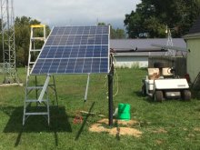
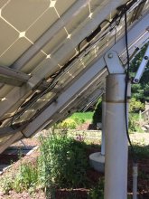
Your project has inspired me! Looks like spring I'll begin to rework my one solar mount. This one is on a 3" pipe. The top can rotate east/west and north/south. But not automatically. Everything is locked down with bolts and hardware.


IMG_1530.jpg
 
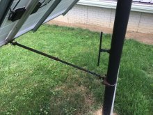
When my wife and I travel, we look for solar arrays. This one came from an Amish house near sugarcreek ohio. There were two of these side-by-side. Notice that there is a pipe that slips over another pipe. The whole shebang rotates. A locking 'T" handle keeps it in place. North/South adjustment is manual with a jack screw. I guess you could automate it with some activators but I have issues with the top pipe simply rotating on the second pipe without a bearing. I could see them cutting into each other.IMG_1543.jpgIMG_1539.jpg
 
Your project has inspired me! Looks like spring I'll begin to rework my one solar mount. This one is on a 3" pipe. The top can rotate east/west and north/south. But not automatically. Everything is locked down with bolts and hardware.


View attachment 30722

Clockwork rotation about vertical axis would give you reasonable time of day tracking and manual seasonal tilt.

Fixing it about vertical axis with horizontal pipe aimed South, manual tilt of pipe for season (or fixed at Latitude), clockwork pivot about pipe axis would give ideal time of day tracking.
 
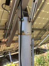
One last photo of a top of pole mount that could be modified for automatic tracking.
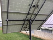
The North/South movement would be quite simple, there already is in place a bracket to adjust seasonally. East/West would be a bit more tricky. This is a 6" pipe and hold 6 250W 60 cells panels.IMG_1646.jpgIMG_1653.jpg
 
Clockwork rotation about vertical axis would give you reasonable time of day tracking and manual seasonal tilt.

Fixing it about vertical axis with horizontal pipe aimed South, manual tilt of pipe for season (or fixed at Latitude), clockwork pivot about pipe axis would give ideal time of day tracking.
I need to figure out how to make a non-moveable rack moveable. I think I'll try and find someone local that will do some welding for me and simply redesign the top pipe holder.
 
One last photo of a top of pole mount that could be modified for automatic tracking.
The North/South movement would be quite simple, there already is in place a bracket to adjust seasonally. East/West would be a bit more tricky. This is a 6" pipe and hold 6 250W 60 cells panels.

Tapered roller bearing, race placed on top of fixed pipe and the cap/bracket riding on inner race.
Cap should be taller to reduce sideways force and friction on fixed pipe.

1608393849794.png
 
Tapered roller bearing, race placed on top of fixed pipe and the cap/bracket riding on inner race.
Cap should be taller to reduce sideways force and friction on fixed pipe.

View attachment 30731
That might be a bit expensive to source a 6" tapered bearing.

I thought about this problem last year, and was wondering if a brake/axle from a heavy duty truck might work.
 
Could neck down to a smaller diameter.
My first though was single steel ball, which makes a point contact. But multiple balls/rollers rolling could be better.

I did a pole-top 4" and welded brackets on a coupling. I though about putting a zerk fitting in the coupling to inject grease into the threads.
Later I expanded the array size and supported with multiple pipes to the ground, fixed mount.
An array with panels of multiple orientations wired in parallel may be more practical than mechanical tracking, given the price of panels these days.
You're absolutely correct! Panels are cheap. However I've always wanted to make a dual axis tracker for no reason other than I think it would be a cool thing to do.
 
You're absolutely correct! Panels are cheap. However I've always wanted to make a dual axis tracker for no reason other than I think it would be a cool thing to do.
You will get a lot more performance out of an E/W single axis tracker, but it looks like you have dual poles holding it in place. There is not much variation N/S in a day, but that will be pretty easy to make an N/S tracker, just replace the solid bracket with a HD linear actuator. Most big stuff all have slewing rotators for the posts to do the E/W.

Here is a DIY kind of large single-axis tracker that works very well.

"The servo is less than $300"

10kW system, 4 arrays of 2500W each.
$300 will get you 1.5kW (STC) from SanTan

What I did like was he had a slope for latitude, so East-West tracking follows the sun well.
A tracker could be geared much lower. It only has to make one revolution per day.

Used an LED as photodetector, he said.
 
Todays output a nice clear day.
Dual-axis tracker 750 Wh
Fixed-panel, seasonally aimed 180° S. 350 Wh.

The 6kN actuator that I have is $67.99, it is much more HD than the one (1200/1600 N) what came with the tracker computer and sensor. But I think the "solar actuator" that Craig Bradley is using is somewhere around 20kN.
 
I found a couple more "Round2its".

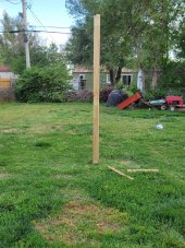
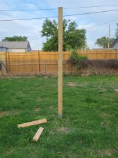
I used a Ground Anchor to put the 4x4x8 in the dirt.
20210508_193200.jpg20210508_193218.jpg

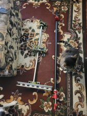
These are the hinges. The short one is N/S the long one is E/W.
The inspector says, "Who cares, give me a treat".
20210508_193054.jpg
 
Nice! Waiting to get larger panels for mine but was planning something very similar with the pillow block bearings. Keep posting updates. Would love to watch it come together.
 
Back
Top