diy solar

diy solar

Making an Online Uninterruptible Power Supply (UPS) using a Lithium Iron Phosphate (LiFePo4) battery.

zaps

New Member
Joined
Jul 4, 2020
Messages
20
I've been thinking about making an online UPS with a LiFePo4 battery. "Online" means the load is running on the inverter even when mains power is available.

To show the general idea, there's a diagram of one below based on a lead-acid battery. The 120VAC mains power on the left drives the battery charger. The battery charger powers the inverter while float charging the battery. For the lead-acid battery, the float voltage in this example is set to 13.8 VDC. The load is running off the inverter, and if mains power is lost, the battery keeps supplying power and the load keeps working, until the battery dies. If the UPS needs to go offline for some reason, the bypass switch allows the load to run directly on commercial power.

The tricky part of using LiFePO4 here seems to be picking a "Goldilocks" float voltage that isn't so high that it harms the battery, yet isn't so low that the battery has low capacity. It's been suggested that 13.0V works, but the tables of voltage vs. capacity aren't encouraging, indicating about 30% capacity.

So I'm wondering:
  1. If I used 13.0V as the float voltage for a LiFePo4-based UPS, what percentage of capacity should I expect that battery to have?
  2. Is lead acid actually better than LiFePo4 for an online UPS?
  3. What am I missing?
Thanks!
online_UPS.png
 
Only from experience with my own lifepo4 battery, my Victron controller pulls it up to 28.4V, holds it there for about 15 mins then releases back to 27V. There is about 300 watts of load on the system and that draws the battery back down to 27V in a matter of minutes so there's not a lot of storage difference by keeping the battery at 27V.

I made an error when I posted 13V in that other thread, whoops, it should have been 13.5V. You would be losing some capacity at 13V.

What you are building there is essentially an all-in-one sans solar. Nice as a project but already available as a commercial product. Take a look at the popular MPP Solar units if you want something towards the lower end of the price scale.
 
@zaps as long as your float voltage is below "full resting". I think it should be fine. I see it as use vs abuse. I'm going with ~3.4 volts per cell.
 
Last edited:
What will you be using for the bypass switch?
 
@sremick: For the bypass switch, I haven't decided on a particular product, but I was thinking along the lines of a manual toggle switch.

@gnubie, @smoothJoey: Thanks for your comments. While pondering the problem I had a "Eureka!" moment. Here's a new block diagram that shows an improved online UPS in a form that could be implemented using either Lead Acid or LiFePo4 batteries:Online_UPS_03.png

The new part in this diagram is the "DC Bus to Battery Interface" (DBBI), shown as the central lighter-blue rectangle. A DBBI controls the charging and discharging of the battery based on the voltage of the DC Bus and the state of the battery. It allows you to safely set the DC Bus's voltage higher than the resting voltage of a LiFePo4 battery, and can also provide high and low voltage and temperature protections for the battery.
 
@sremick: For the bypass switch, I haven't decided on a particular product, but I was thinking along the lines of a manual toggle switch.

@gnubie, @smoothJoey: Thanks for your comments. While pondering the problem I had a "Eureka!" moment. Here's a new block diagram that shows an improved online UPS in a form that could be implemented using either Lead Acid or LiFePo4 batteries:View attachment 17007

The new part in this diagram is the "DC Bus to Battery Interface" (DBBI), shown as the central lighter-blue rectangle. A DBBI controls the charging and discharging of the battery based on the voltage of the DC Bus and the state of the battery. It allows you to safely set the DC Bus's voltage higher than the resting voltage of a LiFePo4 battery, and can also provide high and low voltage and temperature protections for the battery.

Do you have a link or two to these DC Bus to Battery interfaces?
 
@smoothJoey The DC Bus to Battery Interface (DBBI) was just conceived; it hasn't been implemented for LiFePO4 yet. Maybe there's something that does the job of the DBBI for LiFePO4 that someone reading this thread can make us aware of. Otherwise, it may become a DIY project.

For the DIY approach, I think the next steps would be to write up a requirements specification and create a rough draft of the user's manual.
zaps,

Sounds like your making a special interface to control the flow voltages, more like a BMS but a super BMS for UPS inverter to accept universal type batteries. R&D spinning in the head to automate it.

Maybe keep it simple by use the Lead-Acid native charging profile as it is so the load will auto fail over when the AC power is lost.

Some logics:

1. Main power lost -->Failover to Lead-Acid(UPS native charging profile)
2. Main power lost -->an always ON relay that was powered by the AC power is dis-engaged(Off) to run the LifePo4 in parallel for a second and then disconnect the Lead Acid afterward.
2a. The only issue with running it in parallel with different voltage, there is an chance of a big spark.
2b. Maybe put a battery voltage protect to detect the same voltage before parallel to eliminate some risk of spark.

3. Once Main power is back online, the Relay comes back ON, and disconnect the LifePo4 and reconnect the Lead-Acid again using the UPS's native charging profile.

4. Charge the Lifep04 BMS bank via the SCC/AC power.

Many forum members are using UPS as backups but not using the AC wall plug for the reason it will over charge the LiFeP04 batteries.

Keep thinking..
 
@zaps are you imagining something like this?
Perhaps this?
 
A UPS backup inverter synchronizes its phase to the AC power from grid. When grid power goes down the relay flips over to inverter supplying the same phase the grid would have had. This is true even if inverter is just a modified sinewave source.

You should not be using any inverter for this application that will run with random phase relative to grid.

Most computer power supplies these days use power factor correction circuitry that may not take well to a sudden shift in input AC phase.
 
I'm looking to build a 12v always on UPS. I have only DC network and computer components (have a 48v dc switch which I will have a specific 12v to 48v buck boost for that). Trying to build it into a 1u form factor and to use the fortune cells.

I'm going to delve through beginner area but one question is how to auto switch between online power to the battery when mains power goes away...

Side question has anyone tried using the fortune cells horizontally side by side?
 
@burtonmadness I'd be very interested in building something like this, too. I have recently moved from big servers to smaller compute nodes that can off about 19V DC. This has significantly cut my power usage and I am sharing a single PC power supply for multiple servers. Anything, not t hijack the thread, but have been thinking about doing this with LFP cells, too.
 
3.35 vdc per cell for continuous float will be over 90% capacity.
3.30 vdc per cell float is 50% SOC

If battery temp normally >85 deg F ambient temp keep closer to 50%. Higher temp with higher float voltage is greater aging.
 
You can get DC in PicoPSUs that can pump out 450w so unless you are running a high performance gfx card , DC in is possible for .

For me I'm planning a 12 node rasp pi cluster, plus a freenas server with 16 ssds. Idea is to build a portable 4u system I can transport to N RV once we go mobile late next year
 
@smoothJoey The DC Bus to Battery Interface (DBBI) was just conceived; it hasn't been implemented for LiFePO4 yet. Maybe there's something that does the job of the DBBI for LiFePO4 that someone reading this thread can make us aware of. Otherwise, it may become a DIY project.

For the DIY approach, I think the next steps would be to write up a requirements specification and create a rough draft of the user's manual.
@zaps, what you’re looking at already exists in the form of an “online, double conversion” UPS that’s generally used in the commercial market. I happen to be a UPS technician.

Basically, a rectifier is at all times creating a DC current from your utility input source. That DC is what we call the DC link, which is then fed to the inverter that creates its own, new sine wave. The inverter is always synchronizing itself to the input in case of overload or power module failure. This input is also referred to as the bypass source. Internal to the UPS is a static switch, essentially an internal bypass through SCRs that let “raw” utility power through to your loads.

With regard to batteries, modern transformer less UPSs run a different DC link voltage than they do for the battery charging circuit. There’s a buck/boost circuit that allows the batteries to charge or discharge from/to the DC link. With my service software, I can program the UPS to float charge at a particular level and also “dump” the load once the battery voltage reaches a pre-determined low point, to prevent over-discharge.

Take a look at Eaton’s 9155 UPS. That charger runs at around 220VDC when using the internal VRLA (Valve Regulated Lead Acid) batteries.

Hope this info helps!
 
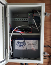
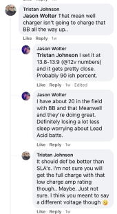
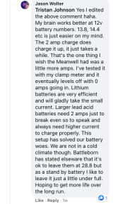
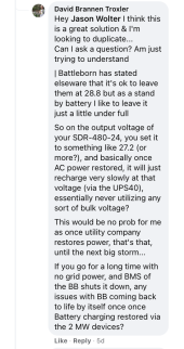
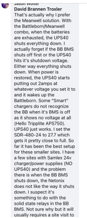
This guy is using a Meanwell DR-UPS40 & Meanwell SDR-480-24..
You could use a 24v inverter off of the SDR-480-24 if AC power needed..
Thoughts on this.. I work in telecom and looking to do the same but not totally sure about this... Y'alls thoughts?
I thought I could just hook a 24 volt load up to a 24v battery +/- terminals with a victron ip-67 (for example) up to the same terminals at same time.. but my understanding of Kirchhoff's law isn't good enough to know why this would or wouldn't work
 

Attachments

  • Screen Shot 2022-01-07 at 7.32.31 PM.png
    Screen Shot 2022-01-07 at 7.32.31 PM.png
    1.3 MB · Views: 28
  • Screen Shot 2022-01-07 at 7.36.57 PM.png
    Screen Shot 2022-01-07 at 7.36.57 PM.png
    374.7 KB · Views: 25
  • Screen Shot 2022-01-07 at 7.37.28 PM.png
    Screen Shot 2022-01-07 at 7.37.28 PM.png
    417.4 KB · Views: 21
  • Screen Shot 2022-01-07 at 7.37.42 PM.png
    Screen Shot 2022-01-07 at 7.37.42 PM.png
    443 KB · Views: 17
  • Screen Shot 2022-01-07 at 7.38.31 PM.png
    Screen Shot 2022-01-07 at 7.38.31 PM.png
    660.9 KB · Views: 21
Back
Top