diy solar

diy solar

Manual Generator Transfer Swith

thundley

New Member
Joined
Oct 23, 2020
Messages
4
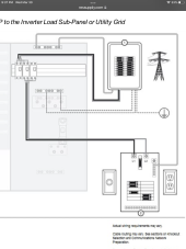
Hi all. I've read the threads on transfer switches and haven't seen what I'm looking for so hoping to get some recommendations here for the off-grid system outlined below that will allow me to run my generator directly to load while bypassing the inverters in the event of failure or maintenance (on the inverters).

Simply installing a two-position switch to switch the load center between the generator and the inverters won't work for me as the generator needs to continually be connected to the inverters (during normal ops) so that it will automatically kick on to charge the batteries if the charge controllers sense low voltage.

I need a manual switch that will switch the generator to the load center while at the same time disconnecting it from the inverters. My apologies for my weak electrical knowledge if this request sounds straightforward.

Here are the specifics of my system:
  • 21.5 kW array
  • Two double-stacked Sol-Ark 12K Hybrid Inverters (combines the inverter and charge controller in one box)
  • Three Fortress e-Vault 18.5 kW batteries
  • 14 kW Kohler BU Generator
Thanks in advance for any recommendations for this switch!
 
I don't yet have a solution for you, but just to be sure, are these the two configurations you need the switch to set?

1611129146032.png

Questions:
  • Are you stacking the two inverters to get 240 Split phase?
  • It looks like the Sol-Ark can have both Grid and Generator. Will the grid be used in your set-up?
  • Do you know if the generator has a bond between Neutral and Ground?
 
Why don't you keep the generator wired to the inverter inputs, don't disconnect when bypassing?
At least, don't disconnect automatically. You can have a manual SPST or DPST switch to isolate inverter input when handling the wires.

I use interlocked breakers in load center to select between two sources (inverter and grid in my case.)

If you really want to do it, could use two DPDT.
One connects generator to either inverter input or second DPDT
Other connects load center to either inverter output or first DPDT.
 
I don't yet have a solution for you, but just to be sure, are these the two configurations you need the switch to set?
Thanks for your reply FilterGuy. Yes, the graphic in your reply is exactly what I'm looking for and my best answers to your other questions are in red below.

  • Are you stacking the two inverters to get 240 Split phase? The stacking of the inverters is to provide me the kW's I need and is 240 split phase. Each inverter puts out 9 kW for a total of 18 kW.
  • It looks like the Sol-Ark can have both Grid and Generator. Will the grid be used in your set-up? I am totally off-grid but by Sol-Arks recommendation I will tie the generator into the grid inputs while the gen input will be unused.
  • Do you know if the generator has a bond between Neutral and Ground? I did not know the answer to this question but googled it and found this on another forum from a user installing a 12 kW Kohler gen set; "while installing the genny and reading the manual, I see that the neutral is bonded to the ground in the generator junction box". I can find nothing in the Kohler spec sheet indicating whether or not it is bonded so I'm going to assume it is.
 
  • Do you know if the generator has a bond between Neutral and Ground? I did not know the answer to this question but googled it and found this on another forum from a user installing a 12 kW Kohler gen set; "while installing the genny and reading the manual, I see that the neutral is bonded to the ground in the generator junction box". I can find nothing in the Kohler spec sheet indicating whether or not it is bonded so I'm going to assume it is.

Assume nothing; check with an ohm meter. Try connecting a light bulb from hot to ground, use DMM to check voltage between neutral and ground.

Whether load center is powered by inverter or generator, neutral and ground should be bonded at exactly one place (for many grid tied systems, this is at the service entrace). This will ensure GFCI outlets turn off all live wires (which assumes neutral isn't hot.) Exactly one place so return currents don't go though a ground wire.
 
Why don't you keep the generator wired to the inverter inputs, don't disconnect when bypassing?
At least, don't disconnect automatically. You can have a manual SPST or DPST switch to isolate inverter input when handling the wires.

I use interlocked breakers in load center to select between two sources (inverter and grid in my case.)

If you really want to do it, could use two DPDT.
One connects generator to either inverter input or second DPDT
Other connects load center to either inverter output or first DPDT.
Thanks Hedges. I'm very new to all of this and have very little electrical background so my apologies for not entirely comprehending your reply. My thought was just a simple transfer switch to manually switch the gen from the inverters to the load center to allow me to run the house on gen only if the inverters fail. Not sure if it's possible but a switch that would at the same time, disconnect the gen from the inverter would accomplish the proper isolations with the throw of one switch. If this is not possible then separate disconnects to the inverters would work as well. Again....my electrical ignorance is showing.

I think NEC code requires a transfer switch on a BU generator is that correct? Not sure what this switch will do in an off-grid system.
 
If you had a grid-connected house and a generator, it would need a transfer switch to ensure the grid was never back-fed by the generator.
Yours is off-grid, and you want to make sure inverter is never back-fed by the generator. Transfer switch (or interlocked breakers in your load panel) would take care of that.

Disconnecting inverter input from generator is a separate issue. Might not ordinarily be needed, but if generator is running and you want to disconnect wires from inverter in order to send it to a shop, a disconnect switch would be convenient.

What I think you need is "simple transfer switch to manually switch the load center from the inverters to the generator"

Can you find an interlock that works with your load center? It would either interlock the main breaker with a backfed branch circuit breaker, or interlock two backfed branch circuit breakers.
 
What I think you need is "simple transfer switch to manually switch the load center from the inverters to the generator"
This makes sense. I would still need a separate disconnect switch to entirely disconnect the gen from the inverters correct?

Can you find an interlock that works with your load center? It would either interlock the main breaker with a backfed branch circuit breaker, or interlock two backfed
branch circuit breakers.
Ugh.....I need to do more research!
 
This makes sense. I would still need a separate disconnect switch to entirely disconnect the gen from the inverters correct?

If the inverter has an AC input as well as output, it has an internal relay to connect/disconnect the generator or grid. You only need a separate disconnect switch if you're going to use a screwdriver on wire terminals while the generator is running (like to uninstall the inverter)

Ugh.....I need to do more research!

This shows a couple I use:


Make sure you select one for your exact model breaker panel.
 
Thanks for your reply FilterGuy. Yes, the graphic in your reply is exactly what I'm looking for and my best answers to your other questions are in red below.

  • Are you stacking the two inverters to get 240 Split phase? The stacking of the inverters is to provide me the kW's I need and is 240 split phase. Each inverter puts out 9 kW for a total of 18 kW.
  • It looks like the Sol-Ark can have both Grid and Generator. Will the grid be used in your set-up? I am totally off-grid but by Sol-Arks recommendation I will tie the generator into the grid inputs while the gen input will be unused.
  • Do you know if the generator has a bond between Neutral and Ground? I did not know the answer to this question but googled it and found this on another forum from a user installing a 12 kW Kohler gen set; "while installing the genny and reading the manual, I see that the neutral is bonded to the ground in the generator junction box". I can find nothing in the Kohler spec sheet indicating whether or not it is bonded so I'm going to assume it is.
OK, Since the Gen-set has a N-G Bond and you are going to wire it as if it is the grid it becomes the single system bonding jumper. Furthermore, since the bond is in only one place, you don't have to switch neutral.

I am not sure I like it, but here is a way to do it using a 4 pole transfer switch. Warning: These switches are expensive!

1611169734585.png

(In the above, the switch is in 'maintenance mode')

Like I said..... I am not sure I like the design...but I can't put my finger on why. Maybe someone else can tell us if this is off base.

If you decide to do this, watch for ground loops. The way I drew it almost certainly would create one. There is also a possibility of a loop on the neutral line that would be a nasty broadcasting antenna for all the noise coming from the inverter. There are ways to get rid of the loops but it would involve some very unconventional AC wiring.

BTW: To remove the inverter safely, you would still want shut everything down while you are unhooking all the wires.
 
Last edited:
My apologies for my weak electrical knowledge if this request sounds straightforward.
You are dealing with deadly voltages. Even if you don't get shocked, there are significant fire hazards if this stuff is done wrong. Please make sure you fully understand this stuff before you do anything. Better yet, get an electrition to review your set-up before you power it on.
 
I would use this switch (or the fusible version) between generator and inverter input:


No need for this switching function to be tied into the transfer switch; each can happen independently
.
As a manual transfer switch to select inverter vs. generator feeding the breaker panel, I would use interlocked breakers.

If the two Sol-Ark are each 120/240V, would want fused or breaker combiner before going to the transfer switch function.
The interlock allows one of two breaker (A/B) to close. It wouldn't support (A/(B & C)) where B and C are for the two inverters.
Connecting the inverters together first, like with yet another breaker panel or DIN mount breakers or fuses takes care of that.
I assume each is supposed to have its own breaker (if not, wires could just splice.)

I've had problems with Square-D QO breakers differing in resistance, so current didn't split evenly (in this case, generator through two paralleled inverters to breaker panel.) I solved that by using two 63A DPST DIN mount breakers, which allowed current to split evenly. I had a fairly long wire providing matched resistance on each path.
 
I have exactly the same requirement as the OP. I am planning on using the Square D safety switch between the gen and inverter and interlocked breakers in my sub panel (in a shed with the inverter, main panel in the cabin neutral/ground bounded at the main panel)
My question is wiring the sub panel interlocked breakers.
My understanding is that at the both the Inverter L1/L2 would be backfed into a DP breaker that is interlocked with another DP breaker backfed front the Generator L1/L2 and the neutrals and grounds from the both the generator and inverter connect in the sub panel to the the same Neutral and Ground bars in the panel, respectively. The main lugs in the sub panel would feed the main panel in the cabin.

Is this the correct wiring configuration?
 
Back
Top