diy solar

diy solar

Manual Transfer Switch

It's not a good choice of thing (without looking at the linked pages at all). Connecting a cable + plug that is rated for 15A to a circuit that is rated to provide 30A leaves you with the very real possibility that damaging current can be drawn over that cable + plug before the supplying circuit will even think about tripping. If there was a 15A fuse at 30A end of the lead that'd cover that situation. This makes no reference to the voltages that may be present on that 30A socket.

Having not read the links at all I'm assuming supply side is 30A, load side is 15, not the other way around.

You always want an appropriately rated fuse protecting the lowest rated component.

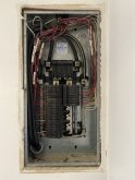
The 115/230V 30A recessed plug would be wired to utility panel for feed by a generator. Cord adapts from that to a standard 15A plug. Standard outlets are normally on a 20A breaker. The 15A/20A sockets take the same plug and one with a blade rotated 90 degrees.

His generator is rated 2200W, a bit under 20A.
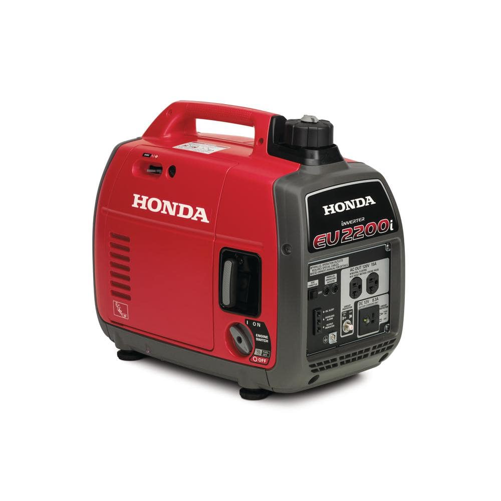

The cord he's looking at isn't even 12 awg (ampacity 30A but overload protection supposed to be 20A). It is 10 awg.
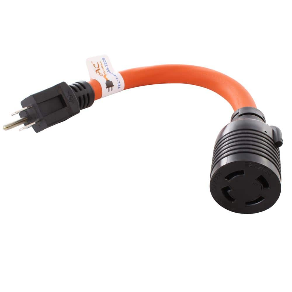

so dmholmes: You aren't supposed to, but I think that cord is offered with a wink and a nudge. Better to open up the inverter and put in a 30A outlet or wire 10 awg. Although 3000W isn't quite 30A, more like 25A. Some may even have breakers; if 20A you ought to keep current draw under 16A to avoid tripping. So DIY hack job would be the thing to do.

The main thing I was worried about was a source capable of 30A or more 120V single phase used to drive both hots in a load panel, because then two 120V circuits might share a neutral return.

I picked up a couple adapters that go both directions. The one with 30A input 15A output has a breaker.
 
The main thing I was worried about was a source capable of 30A or more 120V single phase used to drive both hots in a load panel, because then two 120V circuits might share a neutral return.

I picked up a couple adapters that go both directions. The one with 30A input 15A output has a breaker.

Most of that is over my head. I think I'll stick with the 15A inlet and not try and future-proof for now. But is there no good way to connect to a 30A inlet from a 15A/120V 3 prong plug?
 
No problem powering a 30A inlet from 15A plug, so long as whatever feeds the 15A plug won't deliver much more than 15A.

There can be problems powering one half of a split phase 120V/240V panel (i.e. you just install a 15A inlet wired to one phase in panel). If any 240V appliances are turned on, they will connect that powered phase to the other phase; it and appliances on the other phase see "brown out", low voltage as they each get part of the 120V.

There can also be problems powering both halves of a 120V/240V panel from a single 120V source (what that cord does) if the source can deliver more than 20A. Some house wiring uses red and black for the two legs of 120V/240V, and white for neutral. With 20A breakers, red and black each carry up to 20A, and white carries the difference between red and black, always 20A or less. This cord connects red and black together (not 180 degrees out of phase), so white carries red + black, up to 40A if source can provide it (e.g. 5 kW generator), which is too much.

I would do the 30A 120/240V input, and use that cord (ideally with 20A or 15A breaker in generator or inverter)

For a more powerful source, just make sure it produces 120/240V
 
No problem powering a 30A inlet from 15A plug, so long as whatever feeds the 15A plug won't deliver much more than 15A.

That is not a problem at the moment with my generator and inverter. If we had a larger generator with the locking-type outlet I think that is easy to get a cord that plugs into the 30A inlet.

How do you connect, say a 3000W inverter to the 30A inlet? I don't see any 3 prong to 4 prong adapters that can handle the amperage.

There can be problems powering one half of a split phase 120V/240V panel (i.e. you just install a 15A inlet wired to one phase in panel). If any 240V appliances are turned on, they will connect that powered phase to the other phase; it and appliances on the other phase see "brown out", low voltage as they each get part of the 120V.

There can also be problems powering both halves of a 120V/240V panel from a single 120V source (what that cord does) if the source can deliver more than 20A. Some house wiring uses red and black for the two legs of 120V/240V, and white for neutral. With 20A breakers, red and black each carry up to 20A, and white carries the difference between red and black, always 20A or less. This cord connects red and black together (not 180 degrees out of phase), so white carries red + black, up to 40A if source can provide it (e.g. 5 kW generator), which is too much.

Our panel will have the interlock and new 15-30A (depending on this discussion) breaker installed. I don't really understand the phases, or how they are powered. We have no plans to run 240V appliances but I suppose if we had enough generator in the future we might consider running 1 of the AC units.

I would do the 30A 120/240V input, and use that cord (ideally with 20A or 15A breaker in generator or inverter)

For a more powerful source, just make sure it produces 120/240V

The cord I mentioned earlier?

I hadn't considered adding a breaker for the input into the inlet box, what kind would you add?
 
It isn't the problem with the feed amperes. It is the devices you plug in that determine the amperes through a circuit, or in this case, plug.
 
It isn't the problem with the feed amperes. It is the devices you plug in that determine the amperes through a circuit, or in this case, plug.

Yes of course. The problem is that the cord in question that would adapt from an inverter (3 prong 120v) to a 30A inlet can only handle 1875W max. So with a 3000W inverter for example, you could run a load with more than 1875W into the 30A inlet.
 
Yes of course. The problem is that the cord in question that would adapt from an inverter (3 prong 120v) to a 30A inlet can only handle 1875W max. So with a 3000W inverter for example, you could run a load with more than 1875W into the 30A inlet.

The cord is 10 awg so would carry 30A no sweat:

"This adapter is 1 ft. in length and is an STW, 10/3"

The style of plug is intended for 15A. Another style with one terminal rotated 90 degrees would be intended for 20A.
Sockets of the 15A style may or may not have good enough contact (low resistance) to carry more without heating up.

Ideally, get a 120/240V inverter or generator.

If you connect a 30A 120V or larger source to your house wiring, it has the potential to overheat a neutral wire in the walls (if wired to both halves of the panel), or to damage appliances due to low voltage (if wired to only half the panel.)

The cord in question powers both halves of the panel:

"The NEMA L14-30R (Hots Bridged)"
 
The cord is 10 awg so would carry 30A no sweat:

"This adapter is 1 ft. in length and is an STW, 10/3"

Right, but they also said:

"Maximum operation power of 1875-Watt"

30A at 120V would far exceed that of course. I don't understand why it is limited to 1875W.
 
I should have said, "the wire could carry 30A".

They TOLD you not to exceed 1875W (15A at 125V)
Because that is what NEMA 5-15 is rated for.

The wink and nudge they gave you was the 10 awg wire, which nicely matched the 30A socket.

That way if something bad happens because you exceeding their ratings, it is on you.
 
Looks like it.

But what we do NOT know yet is if it is OK for any of these inverters to have neutral tied to ground. That happens inside your utility panels. Some cheap 120V inverters put out +/-60 on each of hot and neutral, would fry if neutral grounded.

Better to get a 120/240V split-phase inverter. Here are a couple:


I think I got too off track trying to future-proof this setup. So going back to basics, 15A or 20A inlet box with interlock.

Is there an advantage to go with the 20A? The 15A doesn't require an adapter, the 20A would require a adapter (NEMA L14-20).

Is it possible to flush mount the box with the wall? I have only seen them mounted outside the wall.
 
Any one using a 15 or 20 amp plug should be aware of operator error. Do not attach the HD appliance with a 20 amp plug.
 
Looks like it.

But what we do NOT know yet is if it is OK for any of these inverters to have neutral tied to ground. That happens inside your utility panels. Some cheap 120V inverters put out +/-60 on each of hot and neutral, would fry if neutral grounded.

Better to get a 120/240V split-phase inverter. Here are a couple:


Just a question, what is the difference between a generator and inverter? On the directions on my manual transfer switch from Connecitut Electric Emergency transfer switch, it states:
COMPLETING THE INSTALLATION 1) When the preceding steps have been completed for all desired circuits, the EmerGen Switch white (neutral) wire needs to be installed. a. Select any unused hole on the neutral bar in the load center. b. Cut and strip the wire appropriately. Insert the wire into the hole in the neutral bar and tighten securely. 2) The EmerGen Switch green (ground) wire needs to be installed into an unused hole in the ground bar in the load center. a. Select an unused hole in the ground bar in the load center. b. Cut and strip the wire appropriately. Insert the wire into the hole in the ground bar and tighten securely. NOTE: If no separate Ground Bar exists, connect the green wire to an unused position in the Neutral bar.

If this is the case for a generator would it be different for an inverter? Just wondering. I am currently using this box for my solar.
 

Attachments

  • Resized_20200923_085157.jpeg
    Resized_20200923_085157.jpeg
    134.9 KB · Views: 2
  • Resized_20200923_085303.jpeg
    Resized_20200923_085303.jpeg
    158 KB · Views: 2
I think generators commonly have GND terminal of socket tied to generator frame, but isolated from neutral.
When wired to a house, neutral and ground are tied together at the utility service entrance in most cases. Sometimes, elsewhere in the utility grid.
Connecting neutral and ground of generator to neutral and ground bars in breaker panel (or to combined neutral/ground bar in most cases) ensures generator frame is grounded.

Mobile applications like boats and RVs should have a switch inside that connects neutral to ground when not plugged in to shore power. But no connection when they are plugged into shore power because that occurs at the dock/campground. (There are possible safety issues with neutral/ground connection occurring in two different locations.)

Good transformer type inverters will generally be like those generators, with no internal connection from neutral to ground, nor to battery. So could be wired the same.
Some cheap inverters have a connection between the AC terminals and battery, often not neutral to battery but either a midpoint (60V) or they may alternately connect neutral and hot to battery. Probably no good way to use those without adding an isolation transformer.

I'd start with an ohm meter and test the inverter while it is disconnected. Check for continuity between battery terminals, chassis, each pin of AC connection including ground.

Then I'd operate the inverter and check for AC volts and DC volts between those terminals.

Then I'd connect a 120V light bulb between neutral and ground/chassis, and between neutral and battery negative.
If the bulb lights up, you can't wire neutral to ground externally because it would short something out, or drive battery terminals to a dangerous voltage.
If no voltage appears across the bulb, then those wires could be connected together (in your switchbox or panel)
 
  • Like
Reactions: GLC
I think generators commonly have GND terminal of socket tied to generator frame, but isolated from neutral.
When wired to a house, neutral and ground are tied together at the utility service entrance in most cases. Sometimes, elsewhere in the utility grid.
Connecting neutral and ground of generator to neutral and ground bars in breaker panel (or to combined neutral/ground bar in most cases) ensures generator frame is grounded.

Mobile applications like boats and RVs should have a switch inside that connects neutral to ground when not plugged in to shore power. But no connection when they are plugged into shore power because that occurs at the dock/campground. (There are possible safety issues with neutral/ground connection occurring in two different locations.)

Good transformer type inverters will generally be like those generators, with no internal connection from neutral to ground, nor to battery. So could be wired the same.
Some cheap inverters have a connection between the AC terminals and battery, often not neutral to battery but either a midpoint (60V) or they may alternately connect neutral and hot to battery. Probably no good way to use those without adding an isolation transformer.

I'd start with an ohm meter and test the inverter while it is disconnected. Check for continuity between battery terminals, chassis, each pin of AC connection including ground.

Then I'd operate the inverter and check for AC volts and DC volts between those terminals.

Then I'd connect a 120V light bulb between neutral and ground/chassis, and between neutral and battery negative.
If the bulb lights up, you can't wire neutral to ground externally because it would short something out, or drive battery terminals to a dangerous voltage.
If no voltage appears across the bulb, then those wires could be connected together (in your switchbox or panel)
I was watching this guy was was trying to figure out Floating vs Bonded neutrals. Some generators was one way and some were the other way. Trying to relate that to inverters.
 
It would be good to understand 120/240V split phase before connecting a separate transfer switch, because it and your main panel both have that.


Think of it as +120V and -120V, with grounded "neutral" in the middle.

In your box, red and black are mostly used for +120 and -120, and white for neutral. There are a couple exceptions in the branch circuit, white used for a hot. When someone only needs 240V, they use a cable with black, white, bare ground so white goes to the other hot.

We located an interlock for a panel like that somewhere else on this forum. If you can find one (check panel make/model, google that and search this forum for something that fits), then it is pretty easy. A 2-pole breaker goes in two slots next to the main breaker. It gets a sticker warning not to use without cover in place. You use a couple screws to mount interlock on cover. When you use the backfeed breaker, you turn off any circuits like furnace that would draw too much.
 
We located an interlock for a panel like that somewhere else on this forum. If you can find one (check panel make/model, google that and search this forum for something that fits), then it is pretty easy. A 2-pole breaker goes in two slots next to the main breaker. It gets a sticker warning not to use without cover in place. You use a couple screws to mount interlock on cover. When you use the backfeed breaker, you turn off any circuits like furnace that would draw too much.

That was earlier in this thread where you found it, thanks! I also found it here at Amazon and a couple of other places.

I have a quote of about $800 to install either the interlock with inlet or the manual transfer switch, but haven't decided yet.

I like the flexibility of not having to predetermine which circuits can be used with the interlock.

The manual transfer switch installs a little neater since it can be flush mounted like our panel. It also lets me play around with powering circuits without shutting off the main breaker.
 
Why pay $800 to have someone install a $200 kit of interlock and outlet?
You shut off the main breaker, relocate two breakers to the empty space so you can install a 2-pole 15A (or 30A) breaker.

Pick a place for the inlet (below the panel?) and plan to screw it into a stud. Knock out an opening at bottom of panel, put something in hole to protect wire, stuff a short piece of 10/3 + ground wire through the hole an out a hole you've cut in sheetrock behind where inlet goes. Connect red, black, white, bare same way as existing wiring.

Use the template that comes with interlock to drill holes in cover and mount interlock.

Like this, except your breaker is next to the main breaker, and you're wiring an inlet not an outlet.


(one error in that picture - it shows a Homeline breaker but a QO panel, wrong model won't plug in.)
 
Back
Top