diy solar

diy solar

Many here say that an alternator should not be connected to LiFePO4 and that one should use DC-DC Charger

Since you are so convinced, why not buy one, and connect it to a $3000 LiFePO4 bank, and report back in 6 months or a year and let us know how it went? I value experience.

I'm not familiar with that engine. But 5000W is less than 7Hp, so not a very large engine is needed. 223cc should be good for about 10hp. So that spec is not alarming to me.
I will let you know if I can get one with the right charge controller or if I have to make one

You need roughly 2 hp per 1000 watts for reliable operation
A GX200 Honda is rated at 6.5hp peak 1 hour in a 24 hour cycle continues and 5.5 for regular service a 223 is bore and stroked Honda small block heat is an issue.
If you speed them up say 4000 rpm you can get more power out of them, but the rods are short and the side loading is hell on the skirts.
Stock your hard pressed to say what it puts out but I doubt 10 Hp
Just because something like a Champion says its 3500 watts/4000 surge and the engine is a 196 cc clone does not mean it can do that for very long.
A more realistic number is about 3000 after its well broken in loose and still seals yup well.... and there is plenty of fresh cool air around it.

I feel like we have had this conversation before?
Are you a retired school teacher by chance?
 
Just had a thought this morning.........
I´ve 300Ah LiFePo4 & 2 x Trojan t105's. There´s a 25A dc/dc on the way. And a 125A alternator on the engine. Temperature logged & graphed on a Raspberry Pi. Plus a 3Kw invertor.
So.... I think the alternator will be safest hard wired to the Trojans, so why not have the inverter switchable to run off the trojans and plug the mains charger into that when running the engine? Then I should be able to control amps going into the LiFePo4 from zero to 45A (20A mains charger)
Makes sense in my head ??
 
Or just buy a bigger DCDC charger? Renogy makes a 60/30A switchable. Parallel that to the 25A, for lots of switchable options.

There is going to be a lot of losses with the t105s, an inverter, and a mains charger. While you might get 45A into the LFP, the Alternator will be putting out closer to 60A

I can't recommend that hack. Either a larger DCDC charger, or the alternator direct to the LFP. You have a pi connected to the alternator temp? Why not also connect the pi to the alternator to control it. Or buy a proper regulator.
 
My preference is to charge the LFP directly from the alternator with a regulator that can control the output to limit the heat of the alternator case.
 
I do that on my motorhome but how much current are you trying to push through that 12AWG wire?
In the case of my motorhome, I have a 160Ah dumb internally regulated alternator and it is connected to the start LFA batteries. There is an interconnect solinoid that connects the start bank to the LFP house bank when there is a charge current from the alternator. The connection is 2/0 wire with a 90' round-trip distance. given 90' of wire, I do not see more than 60A out to the LFP.
 
On my RV the wire between the engine compartment and the lifepo4 is sufficient to reduce current to well under the alternator's rating.. and the wire is 2x 2ga for most of the distance although it is smaller once it gets under the hood.

I am actually planning to improve the wiring between the alternator and the lifepo4 at some point.

But in the meantime i am absolutely not against using the lead-acid 12v system to power the rv inverter to power the mains charger. Actually have 'bank switching' on the inverter input through a 250a (rated..) 5-terminal relay, so i can switch the inverter from lithium to lead at any time, under load or not. If i'm already driving the v10 RV around, whatever efficiencies are lost in this process are a drop in the bucket of my conspicuous consumption. :ROFLMAO:
 
Not picking on anybody in particular but this was put out as a "you have to" mandate twice in a recent thread. Yes it may be a good option in some cases but it it not the only option and can be very limiting.


https://diysolarforum.com/threads/e...-pv-and-alternator-charging.53005/post-675219

"You don't have to" do anything. Just live with the consequences.

Here are some facts: Large output on an alternator generates heat, running an alternator at full output will cause the alternator to fail due to heat. Lithium chemistry has low resistance and will accept all the amps you give it. Current generates heat.

So the two choices that I see is either regulate the current (along with temperature monitoring) or run without regulating current (and no temp protection) and replace alternators. Nothing wrong with using an alternator directly to charge a lithium based bank as long as the duty cycle of the alternator is not exceeded. In all cases of directly using an alternator on lithium chemistry, I will suggest a temp sensor and controls that will limit output when alternator temp is high. That's just common sense if you understand anything about alternators and lithium chemistry.

You make the decision on how to regulate the current (and temp protection) if you desire to do so. It's a mostly free country so you are free to do as you choose. See line 1 above.
 
On my RV the wire between the engine compartment and the lifepo4 is sufficient to reduce current to well under the alternator's rating.. and the wire is 2x 2ga for most of the distance although it is smaller once it gets under the hood.

I am actually planning to improve the wiring between the alternator and the lifepo4 at some point.

But in the meantime i am absolutely not against using the lead-acid 12v system to power the rv inverter to power the mains charger. Actually have 'bank switching' on the inverter input through a 250a (rated..) 5-terminal relay, so i can switch the inverter from lithium to lead at any time, under load or not. If i'm already driving the v10 RV around, whatever efficiencies are lost in this process are a drop in the bucket of my conspicuous consumption. :ROFLMAO:
Have you measured the voltage under load at the far end where the battery is attached?

You will get some charging but probably not full charge. Which is just fine with LFP. There is just less capacity to draw from.
 
I have not although i assume the lifepo4 would simply hold that voltage to be slightly above whatever its current voltage was and i would have to measure the voltage difference (drop) from front to back of that wiring to get real info. I forgot to mention but the other reason i quickly abandoned direct alternator charging was that i have no easy way implemented to push the alternator regulator’s voltage target higher, because it will spend the majority of its time in the 13s which would hardly be an aggressive charge rate for the 460ah lithium unless the cabling between was ‘ideal’. Same problem with the onboard 120v>12v converter: it never pushes past 13.8-13.9v as far as ive observed, so it wont max its 45a rating into the lithium unless the lithium is already pretty low.

So for now i have settled, happily enough really, on just charging the lithium through the inverter and the ‘mains charger’ while underway if needed. I do plan to upgrade the wiring from under the hood back into the cabin at some point but it is honestly a low priority. I will upgrade the alt charge wire to where the 2x 2ga start, ‘add’ a 3rd 2ga by running 2ga from underhood back to generator start solenoid (<5ft) from where a 2ga run already exists up into the cabin. It will have 2 lugs joined by a stud im the middle, but will still give me a 3rd 2ga from underhood to ‘power center area’. Also need to improve some chassis grounds as i have everything chassis grounded.
 
I have the same situation although my motorhome has 2/0 wires from the start battery to the house battery. The round trip distance from the alternator to the house LFP is about 90'. My alternator is an internally regulated 160Ah alternator but the most I can get to my LFP's even when they are at a low 12.5v is about 60A. The start battery indicates it is getting charged at 14.2v so the alternator is running at set point with the regulator reducing power to maintain 14.2v. With a bit of simple math, the resistance of the 90' of 2/0 and connections is (14.2-12.5) / 60 = 0.28Ohm which seems about right. As the battery gets full, the current going to the LFP bank reduces which lets the voltage go up. Eventually when the battery is completely full, there will be very little current flowing, and the voltage will be near 14.2v.
I call it my long wire regulator. This is only practical because my coach is 40' long with the alternator in the very rear and the LFP battery at the very front.
 
On my RV the wire between the engine compartment and the lifepo4 is sufficient to reduce current to well under the alternator's rating.. and the wire is 2x 2ga for most of the distance although it is smaller once it gets under the hood.
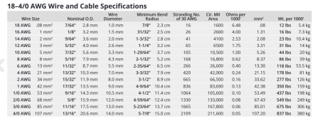
FYI, I have 2/0 wiring on my boat primary circuit but that was too big to connect to the 6mm screws on my EVE cells. Also, the BMS I am using has two terminals for output and my pack is a 2p4s configuration. Given this, it made sense to use two conductors until I get to my shunt or fuse block, but I have the 2/0 from there. I checked the wire gage charts and two 2AWG wires have the exact same area even down to the number of individual strands as a single 2/0.
 
Wow, if someone asked me how they compared i would have been way off, then! Guess i should look at more charts…

Does make me feel better that my 3x 2ga goal should be sufficient for anything id likely want to do. Given that im chassis grounding the lithium, im not even entirely sure the entire vehicle framerail is an equivalently good conductor to 3x 2ga copper. ?
Here is the Ancor wire size chart. I found it very interesting that 2AWG has 665 strands and 66,500 cma which axactly half of 2/0 with 1330 stands and 133,000 cma. Given that it is theoretically possible to insert two 2AWG wires into a 2/0 ring terminal and get a perfect crimp with normal dies.
 

Attachments

  • Ancor wire chart.png
    Ancor wire chart.png
    196.1 KB · Views: 7
My preference is to charge the LFP directly from the alternator with a regulator that can control the output to limit the heat of the alternator case.
Would be mine too. Costs a lot more than the batteries though so not going to happen this week unfortunately.
 
That is not correct. A brand new Balmar 120A alternator with with regulator for less than $950. That much less than I paid for my LFP's.
 
That is not correct. A brand new Balmar 120A alternator with with regulator for less than $950. That much less than I paid for my LFP's.
It is correct - I paid $540 for 4 x 300Ah Catl delivered to Portugal. That´s much less than the cost of a clever alternator & regulator, much as it would be nice to have one ?
 
It is correct - I paid $540 for 4 x 300Ah Catl delivered to Portugal. That´s much less than the cost of a clever alternator & regulator, much as it would be nice to have one ?
Your system is small so it might night not make sense to upgrade your alternator. In that case, I probably would not connect the LFP to the alternator directly because it will likely fry your alt.
 
It is correct - I paid $540 for 4 x 300Ah Catl delivered to Portugal. That´s much less than the cost of a clever alternator & regulator, much as it would be nice to have one ?
You can buy an externally regulated alternator for about $100 or have yours converted, and the balmar ars-5 regulator is ~ $270. A few more dollars for the temp sensor for the alternator. That isn't ideal, but would be better IMHO than other options discussed here.
 
Back
Top