questionsandanswers
New Member
- Joined
- Jun 14, 2021
- Messages
- 4
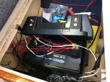
Inspecting battery box on a friend's newly purchased boat:

Looks messy. Any reason why the PV inputs of the battery box would be filled, but all devices are connected directly to + and -? No DC bus?
-Can't find bus bar - should this be bonded? Should it be re-wired so devices are fused through a bonded bus bar, using the box closed? It looks as if in the cabin, each device is individually fused (some lights are directly connected to the batter)
-As far as I know, no inverter present, only DC - anyone seen a setup like this?
-PV inputs filled (unknown capacity). No engine present (sailboat only) so no other means for grounding. Unsure how they are grounded, or if they need to be.
-Battery monitor shows 13.3v float
-Shows full charge but only 36.7 aH capacity- is the battery dying?
Open to suggestions on next steps how to make sure this is usable and safe.


