The way a MPPT controller like your Victron works is that it transforms the raw DC voltage of your solar panels down to what your battery bank wants. What this means is that you may wire panels in series to raise the solar voltage significantly higher then what your battery voltage is. It is usually best to raise the voltage from the panels to the controller has high as possible in order to reduce losses caused by wire resistance, commonly referred to as voltage drop.
Of course though there are limits to this. In your case, you are limited to 150VDC and 60 amperes of current flow. The open circuit voltage of your panels is 49.8, so if you wired 2 in series, you'd have 49.8V X 2 = 99.6V. If you wired either three or four of your panels in series their Voc would be 149.4V and 199.2V respectively. Because voltage goes up on a cold morning, even three panels is too much. So, you want to have two strings of two panels in series, which we normally write as 2S2P.
The general rule of thumb is you don't have to fuse two strings, but you must fuse at least three. I personally prefer using a combiner box with breakers, so I would install a breaker even if I had only 1 string. In your case, you'd want to use a 15 or 20A breaker for each string.
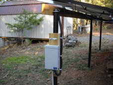
Once the wire from the panel string enters the combiner box, no MC4 connectors are used. The negative (black) wire gets threaded into a negative buss bar. The positive solar wire (red) gets threaded into the bottom of the breaker. In both positive and negative, the bare exposed wire gets screwed down to be held in place so no connectors are involved.
There will be a breaker bar that each breaker is attached to. At the end of the breaker bar, there will be a large screw terminal for attaching a heavy gauge copper wire running from the breaker bar to the charge controller. This wire has to be heavier than each solar wire, because is has to carry the COMBINED amperages of all the strings. In your example it's 12.51A + 12.51A = 25.02A. Look at an ampicity chart like this one to determine how big a wire you need.

en.wikipedia.org
It's common to rate things at least 1.5X then needed, so 25A X 1.5X =37.5A, so looking at the chart, pick at least 8 gauge, which is rated for 40A. It's in your best interest though to go even bigger in gauge, and select 6 or even 4 gauge. You may chose to add more panel strings in the future, and you don't want to have to gut out old wire. Overbuild now so you don't have to retrofit later.
The breaker terminal and also your negative bussbar are likely designed to handle 4 gauge wire, but you need to check what the maximal gauge your controller can handle is. Whatever that gauge is, I'd recommend maxing out to that gauge.
In your case, I would think the most economical stratege would be to mount the combiner as close to the controller as you can, and use 90' strings of lighter solar wire to the combiner, then heavier gauge wire from the combiner to the controller.


