diy solar

diy solar

measuring inrush current.

Roswell Bob

Solar Enthusiast
Joined
Dec 5, 2020
Messages
759
Location
Warner, NH
I need to measure inrush current on my well pump. I don't have a peak reading clamp-on ammeter. I am thinking to use an (off the shelf) AC Current transformer - maybe 100:5. I have DSO to observe. I can use a small value resistor to load the CT and look at it with voltage probe. I also have a DC current probe but only good for 30A. I suppose I can use that to look at secondary of CT. Does this seem a reasonable way to go?
 
A clamp meter would be much easier than lugging around and hooking up an oscilloscope. It's one of those things that you buy, and realize how useful it is to be able to get current readings easily and unobtrusively. I put off getting a clamp meter for a while because I didn't think I would use it much, but it turns out I use it all the time.
 
A clamp meter would be much easier than lugging around and hooking up an oscilloscope. It's one of those things that you buy, and realize how useful it is to be able to get current readings easily and unobtrusively. I put off getting a clamp meter for a while because I didn't think I would use it much, but it turns out I use it all the time.
Thanks for response. I have both AC & DC clamp on ammeters, and yes you are right they are very useful. The problem is they are useless when measuring inrush current. They don't respond to fast transients. I have a huge investment in test gear and software, but mostly retired these days so trying to figure out the inexpensive way. I did find a nice 200a hall effect current sensor in my toy box so I may go with that.
 
if you have a DSO that can store enough samples you should be able to easily capture the inrush waveform.
You probably want at least 2MSa/s and you will need to set the trigger level to go off just as the motor starts up.
Depending on your sensor type you will need to do the math (which should not be that tricky) to go from the voltage measured to amps.
200A range may not be enough, if you have a precision milliohm meter you can make a heavy copper low ohmic power resistor and measure across that directly with your DSO.
 
I need to measure inrush current on my well pump. I don't have a peak reading clamp-on ammeter. I am thinking to use an (off the shelf) AC Current transformer - maybe 100:5. I have DSO to observe. I can use a small value resistor to load the CT and look at it with voltage probe. I also have a DC current probe but only good for 30A. I suppose I can use that to look at secondary of CT. Does this seem a reasonable way to go?

100:5 divides by 20, so shorting the 100 turn winding, 30A reading --> 600A in 5 turn primary. Should work.
Resistor alternately, I guess 10 milliohm would give 300 mV?

Just don't electrocute yourself with the current transformer. You've got a 20:1 voltage boost, but not knowing transformer characteristics I don't know what voltage will develop across it before core saturates. I think I prefer the shorted winding approach.

I used a current transformer meant for line measurement. It had a resistor, outputs 300 mV for 100A.


Also for ripple current in battery cable, and AC consumption of various loads.


I've now got the HF clamp AC/DC ammeter. $100, 1000A max, 10 mA resolution.
It has inrush feature.


if you have a precision milliohm meter you can make a heavy copper low ohmic power resistor and measure across that directly with your DSO.

Two probes, and subtract with math for differential? :)
 
if you have a DSO that can store enough samples you should be able to easily capture the inrush waveform.
You probably want at least 2MSa/s and you will need to set the trigger level to go off just as the motor starts up.
Depending on your sensor type you will need to do the math (which should not be that tricky) to go from the voltage measured to amps.
200A range may not be enough, if you have a precision milliohm meter you can make a heavy copper low ohmic power resistor and measure across that directly with your DSO.
Thanks. I was able to get it measured. I used a 100:1 CT. The inrush on the well pump was about 34ARMS on the 240v line. Quite a bit higher than I would have expected for a 1/2hp motor. FLA is about 6amps - also a bit higher than I expected. My next measurement will be inrush current when I put my inverter onto my battery pack. I have a LeCroy 500MHz Waverunner with a nice math package :)
 
100:5 divides by 20, so shorting the 100 turn winding, 30A reading --> 600A in 5 turn primary. Should work.
Resistor alternately, I guess 10 milliohm would give 300 mV?

Just don't electrocute yourself with the current transformer. You've got a 20:1 voltage boost, but not knowing transformer characteristics I don't know what voltage will develop across it before core saturates. I think I prefer the shorted winding approach.

I used a current transformer meant for line measurement. It had a resistor, outputs 300 mV for 100A.


Also for ripple current in battery cable, and AC consumption of various loads.


I've now got the HF clamp AC/DC ammeter. $100, 1000A max, 10 mA resolution.
It has inrush feature.


Two probes, and subtract with math for differential? :)
What do you have for the AC/DC ammeter? My DC unit is about to give up.
 
I got the Harbor Freight 1000A AC/DC one.
Another member got same model, had flaky voltage readings. Fixed by touching up solder on banana jacks.

 
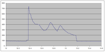
Throwing out another method to measure inrush or surge current. I use a Hantek CC-650 current clamp. It doesn't have a digital readout, but needs to get plugged into a multimeter or scope. That's the primary reason I purchased this probe: it outputs a voltage proportional to measured current. I can then use a scope or datalogger to record the waveform. Here's a current plot of battery current when cranking the engine. There's an initial surge of over 700A, then initial cranking amps vary from 430A to 300A. There's also a constant 95A glow plug current. X-axis is time in minutes.

Start3Current12-30-15.png
 
Back
Top