diy solar

diy solar

Megarevo RxLNA Discussion

Today was all over the place with storms and clear skies. I also disabled grid / pv at certain points for testing.

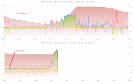
The other charts demonstrate the 2 issues quite well though: No battery discharge and heavy PV throttling after the firmware upgrade.

Thoughts on using my original firmware for APP and the new firmware for BOOT? Everything was working great pre-upgrade except the freezing data feed.
 
I tried to get some results with pysolarmanv5
I have a dedicated linux Single Board Computer (similar to RPI) and it is running Debian linux with Python3

How did you get it to work? use old python?

I have no idea what i'm doing, just trial and error. I am using windows10, and running python scripts in PowerShell.

Code:
""" Scan Modbus registers to find valid registers"""
from pysolarmanv5 import PySolarmanV5, V5FrameError
import umodbus.exceptions


def main():
    modbus = PySolarmanV5(
        "192.168.1.###", 233#######, port=8899, mb_slave_id=1, verbose=False
    )

    print("Scanning holding registers")
    for x in range(5780, 5810):
        try:
            val = modbus.read_holding_registers(register_addr=x, quantity=1)[0]
            print(f"Register: {x:05}\t\tValue: {val:6} ({val:#6x})")
        except (V5FrameError, umodbus.exceptions.IllegalDataAddressError):
            continue
    print("Finished scanning holding registers")


if __name__ == "__main__":
    main()

Produces this..
1659922849717.png


And if you're interested, using that example, I have confirmed 5798 and 5799 to be INV1 temp and INV2 temperature in Celcius. 5800 appears to be temperatue also, but I don't know of what.. 1200 is actually 120.0 (assume volts) followed by 6 (assumed amps). This area of the registers will probably populate for you because they are related to GRID. 5793 may be power factor because 5792 is grid frequency. (it showed 5992 when i connected grid). Anyway, I THINK these registers need to be converted to hex for use HA, at least thats what i've been doing so far.
 
Produces this..


And if you're interested, using that example, I have confirmed 5798 and 5799 to be INV1 temp and INV2 temperature in Celcius. 5800 appears to be temperatue also, but I don't know of what.. 1200 is actually 120.0 (assume volts) followed by 6 (assumed amps). This area of the registers will probably populate for you because they are related to GRID. 5793 may be power factor because 5792 is grid frequency. (it showed 5992 when i connected grid). Anyway, I THINK these registers need to be converted to hex for use HA, at least thats what i've been doing so far.


Maybe you can compare the values with the temp on the display?
IMG_20220807_151141991_crop.jpg
 
Well I'm doing this at my office and the inverters are out in the shop :) I guess I can just remote desktop from my laptop to check. Here are some others i think are correct, please verify.
Code:
Grid Voltage R/U/A            0x3110
Grid Voltage S/V/B            0x3113
Consumption Voltage R/U/A    0x3120
Consumption Voltage S/V/B    0x3124
0x3110 = 12560 is probably L1 grid on display = Grid Voltage R
0x3113 = 12563 is probably L2 grid on display = Grid Voltage S
so for a 3 phase system this would be the next phase
0x3116 = 12566 is probably Grid Voltage T

On the display are L1 & L2 Inv
and
L1 & L2 Load but they are changing so fast, i will have to take some extra measurements/readings later to find the corresponding registers.
Thanks for sharing, really appreciated!
 
And if you're interested, using that example, I have confirmed 5798 and 5799 to be INV1 temp and INV2 temperature in Celcius. 5800 appears to be temperatue also, but I don't know of what.. 1200 is actually 120.0 (assume volts) followed by 6 (assumed amps). This area of the registers will probably populate for you because they are related to GRID. 5793 may be power factor because 5792 is grid frequency. (it showed 5992 when i connected grid). Anyway, I THINK these registers need to be converted to hex for use HA, at least thats what i've been doing so far.

Have you thought about putting a spreadsheet or something similar on google so that people can check/add their findings to it ?
 
Quick update on my issues:
  • CTs were never installed
  • Anti-reverse function was enabled, but my understanding now is that this function requires CTs to work properly
  • I disabled anti-reverse and things started to work as expected both on and off grid
I'm now discussing where to place the CTs. Apparently between meter and main panel will allow me to distribute excess power into my main panel OR feed back to the grid. If they go between the panel and the inverter, the only option is to feed back to grid (not possible to send excess to main panel)

Big thanks to @fromport and the rest of you for helping me get this far!
 
Quick update on my issues:
  • CTs were never installed
oversight from the installer, clearly
  • Anti-reverse function was enabled, but my understanding now is that this function requires CTs to work properly
It does.
garbage in = garbage out (information wise)
Your MR was reading the input of the CT, since they were NOT hooked up it was reading 0.
"ah you are not pulling anything from the grid, i will taper down the PV production to match that since anti-reverse is enabled. I am not supposed to put anything back in the grid"

  • I disabled anti-reverse and things started to work as expected both on and off grid
Wild goose chase before we found that ;-)
I'm now discussing where to place the CTs. Apparently between meter and main panel will allow me to distribute excess power into my main panel OR feed back to the grid. If they go between the panel and the inverter, the only option is to feed back to grid (not possible to send excess to main panel)
correct!
Big thanks to @fromport and the rest of you for helping me get this far!
YW!
 
Anyone experience the inverter turning off battery charging? I am running off grid with no CTs hooked up and also have them disabled. Even in full sun, I keep seeing the battery charging disabled for short periods of time. I have not reached my battery charge voltage yet. Any suggestions why this occurs?

1660332220569.png

1660332296045.png


1660332256766.png
 
Trying to figure out why grid power is being used when there is sufficient PV or battery available.

Last night I set the GRID POWER setting to 0 (from 100)

The result as you can see is that a LOT more grid power was used. Seems quite counter-intuitive. Does anyone understand how these run settings are supposed to work?
 

Attachments

  • gridcompare.png
    gridcompare.png
    201.4 KB · Views: 5
I don't have grid connection. Its my guess that the "GRID POWER" value is what % you are suggesting the inverter supply from battery to try to offset the GRID load. Since you set it to 0, the battery SOC does not decrease in your second chart (0% battery to help offset grid load). In the first chart, since you are asking the inverter to supply as much Battery to the load as it can, you see the battery SOC decrease.

A trial would be a setting in the middle, and see if the battery SOC decrease is a slower rate.
 
How come you don't have a grid connection? Are you back feeding from a different inverter?

EDIT: Disregard this I got confused between the thread and a DM
 
Anyone experience the inverter turning off battery charging?
I was thinking about this, which battery type setting are you using?

I switched mine to Lithium after a firmware upgrade (this setting would not work prior to that upgrade). As far as I can tell, in Lithium mode it will get the charge / discharge / ovp voltages from the BMS. Whereas in Lead-Acid mode, it will allow you to override these settings.
 
I have the intention to order a few more inverters. Since I already have megarevo OEM unit, I am looking at all option.
Looking at the MR website https://www.megarevopower.com/productinfo5.html there is a download in the top left corner with in my case a link to https://www.megarevopower.com/upload/download/2022-07/62d92971dd291.pdf (what a magnificent URL don't you think ? upload/download whatever ;-) )
In that PDF it says


Screenshot from 2022-08-18 07-33-27.png

I have never seen a MR (clone) that has a touch screen.
The Deye has it standard.
Is MR really a clone of a Deye and are they using the sales pitch of Deye to promote their own product even though they don't have this feature?
It is so confusing.
 
I wonder if they are very loosely using the touch "screen" buttons to make that claim? Clearly its not the display that you're touching, but it wouldn't surprise me for them to stretch this definition to be referring to the buttons to make the marketing stats sound more appealing.
 
I have never seen a MR (clone) that has a touch screen.
The Deye has it standard.
Is MR really a clone of a Deye and are they using the sales pitch of Deye to promote their own product even though they don't have this feature?
It is so confusing.
I don't think they have a touch screen, or will offer one anytime soon, as changing the screen (to either touch or color) would likely require them to redo their UL submissions. More time and money. IDK where they are pulling that info from, possibly coping it from their competitor(s)?
 
Back
Top