


SunFarmer
New Member
New member here. I’ve been lurking in the shadows for a few months soaking up knowledge. Been hoping to build a solar electric system for years (maybe even decades), the USA 30% tax credit is a good incentive to finally do it.
Background:
My wife and I live on property in the rural Maryland countryside west of Baltimore in the USA. Our lot is mostly wooded with only a small patch that gets enough sun for solar. Unfortunately, the sunny patch is close to a neighbor’s house, and this neighbor can be prickly. Therefore, I wanted to get a building permit just in case my neighbor complains about the project.
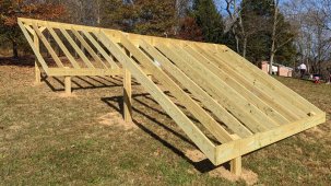
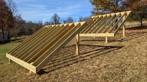
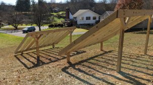
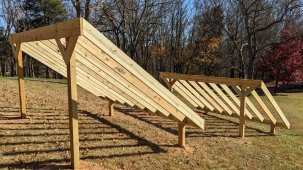
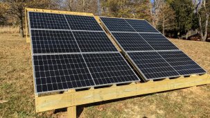
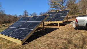
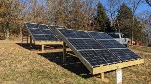
Originally, my plan was to construct a single wooden ground-mount structure to support a dozen panels each in the 450W range. But when I applied for the building permit, I learned about a county zoning requirement for a 30ft setback from my property line. This would have put the array in the shade of some big old trees, which I don’t want to remove. After several more attempts, I reached a compromise of constructing two smaller arrays for six panels each. With this arrangement I got approval to place them 10ft from my property line, where they will enjoy bountiful sunshine.
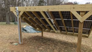
The next hurdle was the building review, where again my design was rejected. I came to learn that the county requires that “accessory structures” have to meet the same snow load strength as actual houses, even though there hasn’t been appreciable snow in these parts for 10 years. Originally, I planned to use 2x8 headers and 2x6 rafters. But to get it approved, I had to seriously beef up my design to use 2x10 headers and 2x8 rafters (and lots of them). The resulting ground-mount structures are overbuilt, but I played along and got the building permit.
Next up is digging a trench for running wires to the house.
Background:
My wife and I live on property in the rural Maryland countryside west of Baltimore in the USA. Our lot is mostly wooded with only a small patch that gets enough sun for solar. Unfortunately, the sunny patch is close to a neighbor’s house, and this neighbor can be prickly. Therefore, I wanted to get a building permit just in case my neighbor complains about the project.
Originally, my plan was to construct a single wooden ground-mount structure to support a dozen panels each in the 450W range. But when I applied for the building permit, I learned about a county zoning requirement for a 30ft setback from my property line. This would have put the array in the shade of some big old trees, which I don’t want to remove. After several more attempts, I reached a compromise of constructing two smaller arrays for six panels each. With this arrangement I got approval to place them 10ft from my property line, where they will enjoy bountiful sunshine.
The next hurdle was the building review, where again my design was rejected. I came to learn that the county requires that “accessory structures” have to meet the same snow load strength as actual houses, even though there hasn’t been appreciable snow in these parts for 10 years. Originally, I planned to use 2x8 headers and 2x6 rafters. But to get it approved, I had to seriously beef up my design to use 2x10 headers and 2x8 rafters (and lots of them). The resulting ground-mount structures are overbuilt, but I played along and got the building permit.
Next up is digging a trench for running wires to the house.


")