diy solar

diy solar

Milk Crate Build Questions (magic smoke)

balikbayan21

New Member
Joined
Jan 17, 2021
Messages
23
I ordered parts almost identical to those in the milk crate battery video
I ordered 4x 10⁵Ah LiFeP04 cells and a 12v 100A LiFeP04 Daly BMS, the Bestek 500w inverter, a 0-48v DC charger, an Alibaba 10a 12/24v MPPT, a bus bar, a fuse block, and a set of usb ports.

I had magic smoke and the inverter died (source of magic smoke), I think I know why but would love input before I wire things back together.

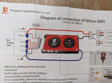
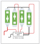
Here is what my BMS/Battery looks like, it matches the diagram sent and I've watched battery build videos so I think I got this right.
bms.PNG

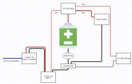
Here was the layout originally, I didn't like how slowly the battery was charging. I set the AC-DC power supply to output either 24v or 14.6v, connected that to the MPPT (in the PV input), then the MPPT connected to the battery and bus bar on negative side. Battery would sit around 13.5v for what seemed like forever, so I got impatient.
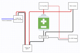
Diagram1.PNG

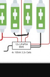
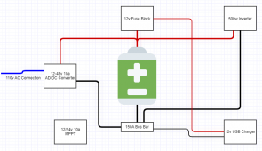
I was thinking that the MPPT might not be passing power to the battery and that because the battery voltage wasn't increasing, the answer was to bypass the MPPT... so I did:
1622082257756.png

My first clue that things weren't right was that the voltage readout on the power supply (AC in, DC out) was no longer adjustable. It simply read the voltage of the battery. I let the battery charge and after about an hour there was a pop, smoke, and I quickly disconnected the negative lead from the battery to the BMS.

I'm fairly confident that going back to include the MPPT is the safe answer. I also picked up a shunt to display voltage in/out.

I'm very open to input and don't want to re-assemble new parts until this is sanity-checked.

Appreciate you all reading this.
 
The bms has a negative lead going to the main battery negative, then a balance lead going to the main negative and each positive. 4 cells in series.
Bms passes that negative out which was connected to the bus bar.
This matches the documentation I was given with the bms
 
The diagrams look simple...
I think you overloaded the power supply.
You state the voltage readout no longer changed after you hooked directly to the batteries.
This is because the CC mode of the supply cannot exceed 10A... so, you tried adjusting the voltage when connected to a MASSIVE load. The voltage cannot change.
What is the resting battery voltage? What is the voltage of each cell? What is the voltage on the BMS terminals?
 
Here's a snapshot of the BMS diagram, I have my cells aligned with the BMS B- connected to the main battery negative and the BMS P- set to connect to a negative bus bar.
1622089658215.png

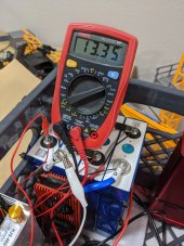
Here's a shot of the BMS and Battery. I'm pretty sure I have this correct, but I'd be happy to be corrected before I break something.
bms2.jpg
 
The diagrams look simple...
I think you overloaded the power supply.
You state the voltage readout no longer changed after you hooked directly to the batteries.
This is because the CC mode of the supply cannot exceed 10A... so, you tried adjusting the voltage when connected to a MASSIVE load. The voltage cannot change.
What is the resting battery voltage? What is the voltage of each cell? What is the voltage on the BMS terminals?
The resting voltage, I'm getting about 13.3 from the P- coming out the BMS and main battery positive (same as main battery negative and main battery positive without going thru BMS).

I'm measuring each cell at 3.32-3.33v

It sounds like for safety, I should connect my AC-DC power supply thru the 10a MPPT then out to batteries. Shunt I bought might give me better info as to capacity and whether I'm charging or not.

I really wish I had purchased a 20a or 30a mppt because charging a 12v battery at 10a is taking a while.
 
100Ah pack .1C is a little slow.

you can charge with the power supply directly, but you HAVE to set the voltage before you connect to the battery, and you cannot set it higher than 3.65Vper cell... make sure you ALWAYS connect to the BMS, not directly to the battery.
 
when you bypassed the mppt what voltage did set the charger to?
and did you adjust it while it was disconnected?
 
100Ah pack .1C is a little slow.

you can charge with the power supply directly, but you HAVE to set the voltage before you connect to the battery, and you cannot set it higher than 3.65Vper cell... make sure you ALWAYS connect to the BMS, not directly to the battery.
Good catch, I misspoke when I didn't mention that the BMS was always connected.

I was powering loads and charging thru the P- lead on the BMS.

If I understand correctly, my cells should handle 3.65v max, which is about 14.6v. Should I just connect with the MPPT like this, let it charge overnight?d3.PNG
 
when you bypassed the mppt what voltage did set the charger to?
and did you adjust it while it was disconnected?
when I bypassed the MPPT (which was likely the mistake) I wasn't able to adjust voltage before or after, the voltage readout on the power supply appeared to mirror the actual voltage of the battery at the time and was rising with the voltage of the battery. 13.31 rose to 13.36 then pop. Not doing that again.
 
Good catch, I misspoke when I didn't mention that the BMS was always connected.

I was powering loads and charging thru the P- lead on the BMS.

If I understand correctly, my cells should handle 3.65v max, which is about 14.6v. Should I just connect with the MPPT like this, let it charge overnight?View attachment 50622
This picture doesn’t show the BMS, but if you are connecting to the BMS outputs in the battery picture, then this should be fine.
 
My charge rate appears to be limited mostly by the amperage the MPPT can send out, which is 10a. So max output is currently 120w (12v@10a), and given a max capacity of 4x10⁵Ah@14.6v (1533Whr) means it will take somewhere around 12hrs to charge. Is that right?
 
Does anyone think the ring connectors for the BMS might be better above the busbars? I'd imagine the contact would be better.
those are easy enough to move, I just stripped about 5mm of the cable and have it sitting between the bus bar and the bare metal poles. I figure it gets good enough contact as is, but if the leads get better contact above vs below, I'm happy to move them.
 
My charge rate appears to be limited mostly by the amperage the MPPT can send out, which is 10a. So max output is currently 120w (12v@10a), and given a max capacity of 4x10⁵Ah@14.6v (1533Whr) means it will take somewhere around 12hrs to charge. Is that right?
That sounds right, but since the cells are not balanced, most likely, the BMS will stop charging when one cell hits 3.65/3.7...
 
Back
Top