diy solar

diy solar

Milk Crate System Expansion Options

bosun120

New Member
Joined
Nov 19, 2021
Messages
29
Hi, new user to the forum here, Will Prowse's Milk Crate video brought me here (probably like many).

I was hoping to try out this build sometime in the future, but had a few questions regarding the system:
  1. I see that Ampere Time, in addition to the 12V/50Ah (600Wh) battery that he recommended, also has larger batteries such as 12V/100Ah & 200Ah. If one wanted to upgrade in the future to a larger Wh battery capacity, would they be able to re-use the same components (inverter, AC charger, etc.) from the rest of the build? Or would certain components need to be upgraded to handle the larger capacity?
  2. Similarly along with increasing Wh capacity, if one wanted to upgrade the AC/Solar input W rating, would one need to use a different MPPT controller or other component?
  3. Would one be able to chain multiples of these 12V/50Ah batteries together (in parallel) to increase the Wh of the overall system, while still re-using the other components?
  4. How would one hook up a battery indicator/meter to display the remaining battery life or time left?
  5. This may be making the project more complicated/expensive, but is there a way to connect an indicator to display the AC input and/or output (in Watts), ie. without having to use a clamp meter? Would something like this Inline Power Meter, with some MC4 connectors added to each end, connected in between the solar panel output & controller input, be able to work (for input at least)?
Thank you, and apologies if these newbie questions have been answered before.
 
Last edited:
Finally, how would one hook up a battery indicator/meter to display the remaining battery life or time left?
Welcome. I will talk about #4 a little.

For my milk crate I use this:


I first had a 25 ah battery and I programmed that. I upgraded to a 50 ah battery and I programmed that. The shunt in line with the negative cable keeps track of the amps in and amps out. I can view AH remaining or a percentage of what is left.

Won‘t display time left on that. For my RV, I have a better, but more expensive Victron Battery monitor that hooks up very similar to the other one, but displays a whole lot more data including time left at the current consumption rate.

The monitor is installed by whatever the instructions are, but most I looked at have you put a shunt as the first thing off the negative terminal. The shunt has a small gauge wire that runs to the positive portion of the battery that will track voltage, and also powers whatever the display you use.

There’s other cheaper battery monitors out there, but most cheap ones I looked the reviews stated they only displayed amps pulled from the battery, or amps entering the battery from the panels, or vice versa, but not both. I want to know how much power is going to the battery from the solar panels as a + or how muchloss there is with a -. The Ali I linked earlier does that.
 
  1. I see that Ampere Time, in addition to the 12V/50Ah (600Wh) battery that he recommended, also has larger batteries such as 12V/100Ah & 200Ah. If one wanted to upgrade in the future to a larger Wh battery capacity, would they be able to re-use the same components (inverter, AC charger, etc.) from the rest of the build? Or would certain components need to be upgraded to handle the larger capacity?
  2. Similarly along with increasing Wh capacity, if one wanted to upgrade the AC/Solar input W rating, would one need to use a different MPPT controller or other component?
  3. Would one be able to chain multiples of these 12V/50Ah batteries together (in parallel) to increase the Wh of the overall system, while still re-using the other components?
  4. Finally, how would one hook up a battery indicator/meter to display the remaining battery life or time left?
The capacity of the battery can be increased without needing to increase the components. The components limit the charge and discharge rate, so if you increase the battey capacity and want to increase the charge and or discharge rate, you will need to increase those components and corresponding wiring gauge.

I started of with 8 280Ah cells to make a 24V battery and 1200W of solar, I quickly decided I wanted more capacity and doubled my battery capacity and increased my solar to 3600W. Now I am heating this office with solar and I am pleasantly surprised I have only had to top up the battery from the grid.

My advise is to start small and use that system to learn for a year or two. Then when you are ready get the components you want for the new system and keep the old one as is for other purposes. The prices will likely come down further and there is no reason why you can't have multiple batteries supplying different parts.
 
Welcome. I will talk about #4 a little.

For my milk crate I use this:


I first had a 25 ah battery and I programmed that. I upgraded to a 50 ah battery and I programmed that. The shunt in line with the negative cable keeps track of the amps in and amps out. I can view AH remaining or a percentage of what is left.

Won‘t display time left on that. For my RV, I have a better, but more expensive Victron Battery monitor that hooks up very similar to the other one, but displays a whole lot more data including time left at the current consumption rate.

The monitor is installed by whatever the instructions are, but most I looked at have you put a shunt as the first thing off the negative terminal. The shunt has a small gauge wire that runs to the positive portion of the battery that will track voltage, and also powers whatever the display you use.

There’s other cheaper battery monitors out there, but most cheap ones I looked the reviews stated they only displayed amps pulled from the battery, or amps entering the battery from the panels, or vice versa, but not both. I want to know how much power is going to the battery from the solar panels as a + or how muchloss there is with a -. The Ali I linked earlier does that.

Thanks for the link & explanation. So if I'm reading the diagram correctly, you have the install the shunt inline of the negative battery terminal (B-)? And then connect a second wire from the positive terminal (B+) to the B+ junction on the shunt, and finally connect the shield wire from the shunt to the display monitor? What AWG wire are you able to use for the small jumper cable (from battery B+ to shunt B+)?

Does the indicator have an auto shutoff feature, or is the standby/sleep consumption so miniscule that it doesn't really have an effect?

51mQaWa6YaL._AC_SL1000_.jpg
 
Last edited:
Sorry had another question, which I edited into the OP:

This may be making the project more complicated/expensive, but is there a way to connect an indicator to display the AC input and/or output (in Watts), ie. without having to use a clamp meter? Would something like this Inline Power Meter, with some MC4 connectors added to each end, connected in between the solar panel output & controller input, be able to work (for input at least)?
 
Last edited:
meter? Would something like this Inline Power Meter, with some MC4 connectors added to each end, connected in between the solar panel output & controller input, be able to work (for input at least)?
I’m not sure if that one will work. Just read the reviews to see if it does all you want. The cheaper ones I looked at did not read everything like positive and negative amps, or left out battery tracking. After installing, I saw that Will uses the Ali in some of his videos. For Solar panel connections, my Victron Charge controllers tell me what I want to see from the panel side without the need for an additional monitor.

Thanks for the link & explanation. So if I'm reading the diagram correctly, you have the install the shunt inline of the negative battery terminal (B-)? And then connect a second wire from the positive terminal (B+) to the B+ junction on the shunt, and finally connect the shield wire from the shunt to the display monitor? What AWG wire are you able to use for the small jumper cable (from battery B+ to shunt B+)?

Does the indicator have an auto shutoff feature, or is the standby/sleep consumption so miniscule that it doesn't really have an effect?
You’re correct in your description of installing.

For the B+ red wire, I used 16 AWG, and that is the biggest I could fit. I did not like that that wire was not included, nut had some red 16 AWG lying around that worked fine.

I use this for my solar generator which I have an off switch for to shut off battery power when stored. It does have a parasitic draw that if left on overnight is so minuscule you won’t notice, but if left on for days or weeks, will start to drain the battery. I forget the draw, could be 50 mV, so yes there is some but not a lot for daily use, but I do not leave the switch on for a storage.
 
I’m not sure if that one will work. Just read the reviews to see if it does all you want. The cheaper ones I looked at did not read everything like positive and negative amps, or left out battery tracking. After installing, I saw that Will uses the Ali in some of his videos. For Solar panel connections, my Victron Charge controllers tell me what I want to see from the panel side without the need for an additional monitor.


You’re correct in your description of installing.

For the B+ red wire, I used 16 AWG, and that is the biggest I could fit. I did not like that that wire was not included, nut had some red 16 AWG lying around that worked fine.

I use this for my solar generator which I have an off switch for to shut off battery power when stored. It does have a parasitic draw that if left on overnight is so minuscule you won’t notice, but if left on for days or weeks, will start to drain the battery. I forget the draw, could be 50 mV, so yes there is some but not a lot for daily use, but I do not leave the switch on for a storage.

Thanks @chrisski, would you be able to share the on/off switch that you used for your system?

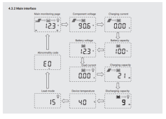
Also, I just read the user manual for the Rich Solar charge controller recommended, and it looks like the LCD interface can display both input voltage/current, battery capacity (%), and discharging capacity (Ah), which means it pretty much does everything I was looking for (except a shutoff switch).

Capture.PNG
 
Last edited:
This is the on off switch


For battery state, the SCC would give you a guess, maybe close, but the shunt will be accurate.

The SCC can’t track SOC from current off the battery, only voltage, and voltage is not the best indicator.
 
This is the on off switch


For battery state, the SCC would give you a guess, maybe close, but the shunt will be accurate.

The SCC can’t track SOC from current off the battery, only voltage, and voltage is not the best indicator.
Thanks @chrisski, not sure I understand why the shunt meter would be more accurate than the SCC, if both are hooked up to the same terminals on the battery?

Is it because the shunt is connected directly to the battery B+, while the SCC is connected through a 25A fuse? Or is there some hardware in the shunt that can read more accurately than the SCC?
 
I have to say this forum/community has been one of the most newbie-friendly I have ever been to.
I agree. They kept me on the right track when I was starting out at the beginning of last year.

This is the build I did for a milkcrate. I use this once or twice a week to cook in a crock pot:


Always tinkering with it. Next will be Adding a third bank of panels to it so I can cook with it all day long while I'm away at work by pointing one set to the East, One to the West, and one to the South. When I started at the end of summer, I did not need to move the panels all day, but with the angle of the sun and short day in the winter, I make half the power at the end of November that I did in September.
 
@chrisski

Though the guide/YT video did not have any links, I was looking to find XT60 connectors & MC4/XT60 cables for the PV+/- ports on the SCC:

XT60 pigtail connector: https://www.amazon.com/Female-Connector-Housing-Silicon-Battery/dp/B073QJWVVK/
MC4/XT60 cable: https://www.amazon.com/PolyEnergy-ChargeCable-Connector-EFDELTA-Portable-Generator/dp/B08RYQKCLT/

I noticed that both connector/cable are 12AWG wire. My plan is to ultimately hook up 2 100W Solar Panels (ie. Renogy 100D) in Parallel, through the aforementioned MC4/XT60 cable and pigtail connector into the SCC. Would the 12AWG wire be able to handle the max current from both 100W Panels in Parallel?

Thanks.
 
@chrisski

Also, I was reading the reviews for the AiLi and similar QWORK battery meters, and there were some critical reviews of it failing prematurely after a few months, with no warranty support.

Have your experienced this with your own system? Would it be better worth to upgrade to something like this Renogy monitor?
 
Would the 12AWG wire be able to handle the max current from both 100W Panels in Parallel?
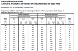
12AWG is rated up to 20 Amp, 200W solar would produce 17Amp at 12Volts (200W / 12V) So yes it can. You should make sure that the cable is UV rated though.
 
This is the on off switch


For battery state, the SCC would give you a guess, maybe close, but the shunt will be accurate.

The SCC can’t track SOC from current off the battery, only voltage, and voltage is not the best indicator.
@chrisski

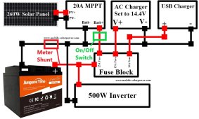
Reading the reviews, sounds like there is not much instruction on how to connect this switch. Looking at the milk crate diagram, would it be best to connect the switch inline between the battery B- and SCC B- terminals (before the battery meter shunt)?

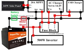
With the additional components of the battery switch & battery meter shunt, would the wiring diagram end up looking something like below?

milk-crate-11_orig.jpg
 
would it be best to connect the switch inline between the battery B- and SCC B- terminals (before the battery meter shunt)?
The couple of builds I did, I put the Master off Switch after the Fuse on the positive side:

Battery Positive terminal--> Battery Fuse --> Switch ---> Busbar

Its OK to have the Shunt have a tiny wire to the Battery positive also.

The switch I link is not the best switch, and is not UL rated. For my RV I use this switch:


Basically the same thing, except UL rated and more expensive and bigger.

I noticed that both connector/cable are 12AWG wire. My plan is to ultimately hook up 2 100W Solar Panels (ie. Renogy 100D) in Parallel, through the aforementioned MC4/XT60 cable and pigtail connector into the SCC. Would the 12AWG wire be able to handle the max current from both 100W Panels in Parallel?

XT-60s w/ 12 AWG wire are fine.

Two panels 100 watts each can only put out around 12 amps of power, under the rated ampacity for 12 AWG and the XT=60 COnnectors:

1637527040386.png
 
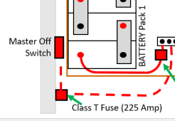
I would add a main battery fuse immediately after the battery positive and then the switch. In my case, I am using a 40 amp main battery fuse like this:

Battery Positive terminal--> Battery Fuse --> Switch ---> Busbar

I had the Solar panel routed through its own wire with its own fuse to a busbar. I'd never thought of fusing it through the fuse block, but that may work if everything is rated to 25 amps.

Where you place the battery meter is wherever you want it. Does not have to be between the fuse block and MPPT. The battery meter will have a cabel going back to the shunt.
Also what is the difference between UL and non-UL rated? More to do with an electrical safety issue? I see in your Crate Build you used the non-UL switch, did you end up switching it out?
I kept the non-UL switch in the crate build. I am only using 35 amps tops through this switch.
 

Attachments

  • 1637532513089.png
    1637532513089.png
    17 KB · Views: 4
I would add a main battery fuse immediately after the battery positive and then the switch. In my case, I am using a 40 amp main battery fuse like this:

Battery Positive terminal--> Battery Fuse --> Switch ---> Busbar

I had the Solar panel routed through its own wire with its own fuse to a busbar. I'd never thought of fusing it through the fuse block, but that may work if everything is rated to 25 amps.

Where you place the battery meter is wherever you want it. Does not have to be between the fuse block and MPPT. The battery meter will have a cabel going back to the shunt.

I kept the non-UL switch in the crate build. I am only using 35 amps tops through this switch.

@chrisski My bad, I mislabeled the previous wiring diagram. What I meant by Battery Meter, should have been labeled the On/Off switch.

I have re-drawn the diagram, would the following wiring connections be able to work sufficiently?

Meter Shunt: https://www.amazon.com/dp/B07CTKYFTG?psc=1
On/Off Switch (UL rated): https://www.amazon.com/Blue-Sea-Systems-Battery-Switch/dp/B00558LSJE/?th=1

milk-crate-11_orig (1).jpg
 
Recommend putting the on off switch immediately after the positive with a fuse before.

If that is your only on off switch and you keep it by the SCC, electricity can still flow. Maybe the inverter, maybe just normal parasitic draw, but current can flow. My RV parasitic draw is .5 amps, which will kill the pictured battery in a few days.

THe switch is next to the battery to keep all loads off when in storage or to shut it down in case of emergency.
 
Back
Top