diy solar

diy solar

Monitoring Jakiper ( maybe SOK too?) server rack batteries via modbus to Esp8266 mqtt

Lardino

New Member
Joined
Mar 22, 2022
Messages
82
I have been trying to monitor Jakiper server rack battery model JK48V100 via RS-485. The RS-485A port is programmable using Jakiper software. You can set it up to work with certain inverters using the Pbms Tools software that Jakiper provides . You need to connect to the RS-232 jack to use the Pbms Tools software. It is actually good software and provides most of the bms information anyone would want. It shows all the individucal cell voltages in a battery, if the cells are balancing, battery SOC, SOH, battery voltage, current going into or out of the battery, temperatures, and more. If you have the batteries stacked and interconnected using the RS-485B and C jacks then you can use the bms software to switch to each server rack battery for it's information.

The reason I want to get the RS-485 data is because I want to be able to monitor and log the data to a raspberry pi running grafana . I do this now using and esp8266 to rs-485 modbus of Peacefair PZEM-016 and PZEM-014 that monitor my Outback inverter output. I also monitor Midnite Classic controllers via tcp modbus and it also gets to the pi to graph using Grafana.

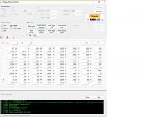
I want to be clear - I don't want to change any settings on the Jakiper bms - only monitor it. I was using some Windows Modbus tools to find available data from the RS-485A port. My connection is plugged in to the battery rs-485a jack and then using the correct wires to a RS-485 to USB adapter. The funny thing is that I couldn't get any valid data from the battery rs-485a jack trying the various inverter options using Pbms software - until I programmed it for Growatt Can . Suddenly the data showed up on the RS-485A jack . This makes me wonder if the trouble others have been having getting their inverters to work with Jakiper battery is because the label on the Pbms software for inverter setup is wrong ? Not sure - i don't have a Growatt inverter. I only know that I got the following results which I will attach pictures of .

My next step is to try and adapt some other modbus to esp8266 projects to work with this battery and be able to send the battery data out on wifi as mqtt. I am a novice at trying to accomplish anything like this and get a bit lost in the code. I thought I would share what I have found so far in case anyone else is interested or would like to help with this project. I mentioned the SOK batteries because they use the same type Pace bms in them. But I have no idea if it would work on them or not.
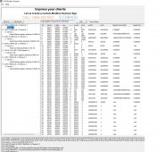
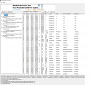
See photos below for what I have accomplished so far. If you look at lines 16 to 31 you can see that it is reporting the individual cell voltages. Thanks for any info or help .
 

Attachments

  • modbus tool.jpg
    modbus tool.jpg
    224 KB · Views: 145
  • modbus scanner 1.jpg
    modbus scanner 1.jpg
    408.4 KB · Views: 137
  • Modbus Scanner 2.jpg
    Modbus Scanner 2.jpg
    418.6 KB · Views: 129
Good luck with your project and please keep us posted!

What level of experience do you have with Modbus? I don't want to make stupid recommendations or troubleshooting tips if you have more knowledge than me... but I am happy to chip in my limited experience!

I would actually love to get someone to make an ESP32 based device to provide a web gui (as well as Influx or MQTT upload) for those of us that don't do Windows. Programming capability would be nice... but not absolutely needed.
 
Good luck with your project and please keep us posted!

What level of experience do you have with Modbus? I don't want to make stupid recommendations or troubleshooting tips if you have more knowledge than me... but I am happy to chip in my limited experience!
I am very novice when it comes to Modbus . I have only made it work for me in past because I could use other projects that were already written.
I was lucky that the Tasmota esp software supports the PZEM devices as well as many others - just connect and pick the right device and it works !
I made a youtube video about that
 
It appears this is the same BMS that's in the EG4 batteries? I've been tinkering with the rs-485 port, and the PC communication software appears to be using modbus rtu. I was able to sniff the connection and deduce a few useful values. It looks like the jakiper is the same, and perhaps so is the SOK. I really wish they would just publish the modbus mapping. I used a raspberry pi and node-red to get the data out via MQTT to a cloud server, so I can remotely monitor the SOC%, voltage, and current. Fun stuff!eg4.jpg
 
rem_electric
I am pretty sure that EG4 uses a Seplos BMS and the Jakiper uses Pace BMS. You will notice that on EG4 the front jacks are a bit different.
There is a topic about Seplos BMS that may be helpful for you.
There is also a project on github that is made for seplos that takes all the data into a web accessible page using esp8266
All these bms put out data in the certain inverters format so for the Growatt that modbus protocol is published.
 
Last edited:
There is also a project on github that is made for seplos that takes all the data into a web accessible page using esp8266
Very cool. I have been looking for something like this.
 
There is a Jakiper monitoring project now on Github that I am helping with. It is a work in progress so if you would like to try or contribute check this out https://github.com/ClassicDIY/PylonToMQTT . Thanks to Graham on ClassicDIY who wrote the esp32 code to make this work.
I am trying to get up to speed on learning how to use VS Code and Platformio . ( edited post to new link for project )
 
Last edited:
It would be great if there was more work done to use ESP devices rather than Pi's as they seem to be out of stock everywhere.
 
It would be great if there was more work done to use ESP devices rather than Pi's as they seem to be out of stock everywhere.
yes this is using an esp32 . But the Pi is also needed later on because I use that to gather,store, and display the graphs of data. You are right about not being able to find a Pi now but at least I have a Pi3B+ that has been working well for me - stable running mosquito, telegraf, influx, and grafana without a glitch for many months.
 
I have a Pi3 too but it suffered the random 3.3v regulator death.
There must be something else that can do it's job locally.
I know enough to know I can't program, just copy code and hope it works !!!
 
I have a Pi3 too but it suffered the random 3.3v regulator death.
There must be something else that can do it's job locally.
I know enough to know I can't program, just copy code and hope it works !!!
I understand what you say. I spent a lot of late nights this past winter figuring out how to make things work. I have a few videos on my youtube page with details of using esp to connect to PZEM energy monitors and then get that data to a pi . Lucky for me , the first part of getting the code onto esp device was simple using Tasmota firmware and that supported the PZEM. I had help from some pro programmers when I needed it to get the pi part of it all working and was using their code to start with too. Here is first part of one of the videos if you are interested.
 
rem_electric
I am pretty sure that EG4 uses a Seplos BMS and the Jakiper uses Pace BMS. You will notice that on EG4 the front jacks are a bit different.
There is a topic about Seplos BMS that may be helpful for you.
There is also a project on github that is made for seplos that takes all the data into a web accessible page using esp8266
All these bms put out data in the certain inverters format so for the Growatt that modbus protocol is published.
by looking at the videos posted, neither the eg4, gyll nor eg4-ll are using the seplos bms's
 
Success ! I am getting mqtt data from the bms now via esp32 plugged into the RS485 A port that is programmed to be Growatt Can.
1663795490496.png
 
Success ! I am getting mqtt data from the bms now via esp32 plugged into the RS485 A port that is programmed to be Growatt Can.
I love (and HATE) the ESP boards everywhere. I've been stuck trying to re-flash a bunch of Sonoff S31 for close to a year. But, I'm working on a Mitsubish Mr. Slim controller with an ESP8266 that is going a bit more smoothly (so far). No idea what is wrong with the S31's; I flashed 6 of them a few years back with minimal pain. Oh well.
 
I got the MQTT data from Jakiper onto Raspberry Pi running mosquito, telegraf, influxdb, and grafana.
Here is the first quick graph I made and will add more to it later. This shows part of absorb, then float . Tomorrow I will get the whole charge cycle showing . The cells still need more cycles to balance after Jakiper changed settings for me on the bms a day ago. It does seem like the new balance settings have helped . But now it will be so much easier to monitor. Next steps for monitor software will be to get data from all three Jakiper batteries. This is a good start though.
1663867359122.png
 
I got the MQTT data from Jakiper onto Raspberry Pi running mosquito, telegraf, influxdb, and grafana.
Here is the first quick graph I made and will add more to it later. This shows part of absorb, then float . Tomorrow I will get the whole charge cycle showing . The cells still need more cycles to balance after Jakiper changed settings for me on the bms a day ago. It does seem like the new balance settings have helped . But now it will be so much easier to monitor. Next steps for monitor software will be to get data from all three Jakiper batteries. This is a good start though.
View attachment 113036
I would love to do the same thing for my SOK battery. Is there a brief write up of what is required to accomplish this? Does the graphing have to be a raspberry pi? I have dockers and VMs I can run.
 
I would love to do the same thing for my SOK battery. Is there a brief write up of what is required to accomplish this? Does the graphing have to be a raspberry pi? I have dockers and VMs I can run.
I can document it better later. But the hookup to the battery is pretty simple. I used an rs485 to ttl adapter . You just bring two wires from the RS485 jack A . The jack A has to be programmed using the SOK or Jakiper software to Growatt inverter output for this to work since it is getting the Growatt modbus data. So the battery outputs RS485 and the two wires are labeled A and B. These connect to the A and B jack on the adapter. The other wires of the adapter go to esp32 3.3v , ground, and tx rx pins. This is the board that I use - they don't cost too much. https://www.amazon.com/HiLetgo-Reciprocal-Hardware-Automatic-Converter/dp/B082Y19KV9/ref=sr_1_6?crid=2VFGQWGF1O1PP&keywords=rs485+to+ttl+converter&qid=1663871108&sprefix=rs485+to+ttl+,aps,293&sr=8-6
Yes you should be able to use a computer running the programs to do it. I only know the specifics for using a Raspberry Pi though.
I do use Docker on the Pi . Someone wrote a program that simplifies and automates downloading and installing the programs needed on the Pi.
The Esp32 gets the data from battery, then sends it out as MQTT . You can direct the MQTT to either external or internal broker . I use the mosquito running the Pi, then the Telegraf program gets that from Mosquito, and sends it to Influxdb which gets it to Grafana. Sounds more complicated than it is since they all work together pretty well once set up.
If you look at the youtube link I posted yesterday , I show same sort of setup to esp32, then in another video I explain how to set up the software to get data, and then also I think in another video or same one I show how to get the data into Grafana .
 
Here is the transition this morning to absorb voltage where you can see the cell voltages diverge. There was a 30 minute absorb time but the cells do not balance the whole time since the bms cuts off the current and balancing stops. Towards the end I raised the absorb voltage to 56v and you can see that rise on the graph. At the end it times out absorb and goes to float voltage of 54 but charge controller goes to resting( provides no current) until battery voltage drops to 54v . That is why it is showing negative current from battery to supply loads.
Here is video showing Jakiper software when this graph is made. I switch to battery 2 and battery 3 but don't have those graphed - working in the esp software - well Graham is working on it to find a way to show all 3 batteries from single esp32 - not sure if that is possible yet.
1663950961988.png
 
Last edited:
Back
Top