diy solar

diy solar

Moving forward with solar

I think it was just following up on what I suggested in #16. Seems the "AC load out" on the sol-ark is "only" rated 50 amps continuous.

When the grid is out it would be okay for the AC load out to power the shop since it won't deliver more than 50 amps.

But, if in normal operation (e.g., grid up) the shop draws more than that it would constantly be tripping the sol-ark breaker. So, for normal operation, a bypass is needed for the shop.

Let's look at the case where it would work, say the shop subpanel was a maximum of 45 amps and the case where it wouldn't work:
If it were less (say 45 amps) then it could be wired like this:

Here the built in transfer switch handles the shop.
But... if the shop subpanel is 100 amps. Then they need to bypass so they have full power when the grid is available.

Note: only 1 phase is shown in the diagram for simplicity with a DPDT. In practice, you'd want one switch flick to change L1 & L2 simultaneously ...possibly this.

Hope that helps!

The picture on the right hand side is exactly what I came up with although I will admit that my hand sketching was not nearly a nice as yours. (8 In fact I think I will copy and paste that in case the inspector wants to see what I am trying to do. For anyone interested the parts I used to accomplish the above are shown in the attachment on post 10.

Because I am a practical kind of guy, after thinking this trough, I decided to approach the shop in a very simple way. For the welder I am simply going to look around on craigslist for a cheap mig welder that may even run on 110 volt. And the same for the air compressor. I don't need a 5 hp for emergency use. So when the grid is down I can still have something that will keep me up and running in some fashion, without risking the Inverter right at the time when you need it the most.

I am also thinking that I will research solar hot water tanks or perhaps separate solar panels specifically for the hot water tank to try and lower the daily load on the Inverter. I one time heard of someone who wired the hot water tank in such a way that one element was on grid and the other on solar. I tried to google that but haven't found it. Any thoughts on that?

And thank you for helping... I am hoping that this thread will also help others.

Les
 
... I will admit that my hand sketching was not nearly a nice as yours.
See Drawing Tools ; -) That was made from the OpenOffice tool which is an open-source replacement for the Microsoft Office suite (used the visio-like tool). But the Wiki page lists a lot of them.

I am also thinking that I will research solar hot water tanks or perhaps separate solar panels specifically for the hot water tank to try and lower the daily load on the Inverter.
I'd wait. You might find by 1 pm your batteries are charged and you're just throwing away solar power. Plus excess electricity is more versatile than excess hot water (you might have an EV in a decade).

I one time heard of someone who wired the hot water tank in such a way that one element was on grid and the other on solar. I tried to google that but haven't found it. Any thoughts on that?
Not pleasant ones. If you're grid-tied you're always using solar power first and exporting excess so no need.
If the grid is out I'd want finer control because of cloudy days.

My interim solution is to just control when the water heater comes on via the breaker box. My long-term solution is to automate the hot-water tank and EV to come on when there's sufficient excess energy. Lot's of people have already set that up via something like home-assistant, but like any good politician I'm waiting for a disaster before I can get myself to spend the $$.
 
Let’s start with an example. We have a 200 Amp bus rating for our service panel. In it, we have a 200 Amp main breaker.

200A x 1.2 - 200A = 40A

See Drawing Tools ; -) That was made from the OpenOffice tool which is an open-source replacement for the Microsoft Office suite (used the visio-like tool). But the Wiki page lists a lot of them.


I'd wait. You might find by 1 pm your batteries are charged and you're just throwing away solar power. Plus excess electricity is more versatile than excess hot water (you might have an EV in a decade).


Not pleasant ones. If you're grid-tied you're always using solar power first and exporting excess so no need.
If the grid is out I'd want finer control because of cloudy days.

My interim solution is to just control when the water heater comes on via the breaker box. My long-term solution is to automate the hot-water tank and EV to come on when there's sufficient excess energy. Lot's of people have already set that up via something like home-assistant, but like any good politician I'm waiting for a disaster before I can get myself to spend the $$.
Those drawing tools were cool... Thank you.

So here is a topic I have left on the backburner but need to look at. The 120% rule. Here is an example of it that actually represents pretty much my situation. This is a quote from Greeentech.

(Busbar Rating (A) x 1.2) - Main Breaker Rating (A) = Max PV (A)

Let’s start with an example. We have a 200 Amp bus rating for our service panel. In it, we have a 200 Amp main breaker.

200A x 1.2 - 200A = 40A
In this example, the maximum output of our PV system can be 40A or approximately 9.6kW. This would satisfy the busbar rating without an issue. However, in many instances there is a need or desire to have a much larger system, so what then?

If we exceed the rating of the busbar without regard to the 120% rule, we are creating a scenario where we are feeding a panel board with too much energy and have nothing in place to prevent the sum of the loads in that panel from drawing more current than the busbar can handle.

I have a 200 Amp service panel but in this case the Solark 12k Inverter is fed with a 60 Amp breaker. That is over the 120% rule as shown here. So what are my options?

Thanks in advance

Les
 
Hmmm... the article does go on to say that you can install a smaller 175 amp curcuit breaker but that leaves me more confused than ever simple because if you add up all of the curcuit breakers in that panel the total is over 500 amps. It sounds like you should be a LOT more worried about that. Putting a smaller main breaker sounds counter productive.
 
...I have a 200 Amp service panel ... 60 Amp [PV] ... over the 120% rule ... what are my options?
  1. Replace the panel or add a second panel (rather expensive and not needed)
  2. Replace the main breaker with a 175 Amps (175+60=235 < 240) (pretty easy/cheap but cuts night-time power to under <= 175 amps)
  3. A Line-Side Tap (probably the most practical and possibly the cheapest).
What is a line-side tap you ask?

It means putting the L1/L2 connection from the inverter between the 200 amp breaker in the load center and the meter. The 120% rule only applies when it's across the load center's backplane, with a tap you can't go wrong. If you do the math you'll see you can never overload anything that way.

The image to the right shows a line-side tap to give the idea.

Knowledgable & DIY Friendly building inspectors /codes will let you do lugs if there's plenty of room in the load center because there's a breaker in the Sol-Ark. Lugs are an inexpensive (?) /simple way to go. In this setup L1/2 from the inverter connect to the supply side of the breaker in the load center.

But not all inspectors are that savvy and may tell you can't do it. They may try and disallow the line side tap altogether. Or your load center may just not be able to support it.
Example of a line-side tap with maximum components
Screen%20Shot%202014-07-15%20at%2010.27.05%20AM.png

You'll probably want an electrician to do this for you anyway as either the service meter needs to be pulled or you have to turn the power off at the pole to make it safe to work on. A certified electrician also can get away with things an inspector would fail if a DIYer did regardless of how safe it is.
 
Last edited:
  1. Replace the panel or add a second panel (rather expensive and not needed)
  2. Replace the main breaker with a 175 Amps (175+60=235 < 240) (pretty easy/cheap but cuts night-time power to under <= 175 amps)
  3. A Line-Side Tap (probably the most practical and possibly the cheapest).

You'll probably want an electrician to do this for you anyway as either the service meter needs to be pulled or you have to turn the power off at the pole to make it safe to work on. A certified electrician also can get away with things an inspector would fail if a DIYer did regardless of how safe it is.


I looked at breakers for my panel... $250.00 or more :love:
 
40A PV breaker, but only operate up to 80% for continuous current, 32A inverter output x 240V = 7680W
Therefore, a number of inverters of that rating.

You're aren't likely to find a 175A main breaker. I'm aware of 200A and 150A for one particular panel I have.

"Line side tap" is one approach, another circuit taken off between main breaker and meter.
That may be accomplished with an insulation piercing connector.
There are meter socket adapters available with an extra tap. My utility PG&E offered that, but 40A max.
 
I recognize that a 12 K system with 9000 watts

-lights and basic household plugs which run your computers etc
- fridges and freezers
- well pump.... we must have water, deep well @30Amp
- hot water tank.... at the end of the day someone needs a shower
- shop... the breakers for the air compressor can be left off most the time

We do have battery storage for up to one week and possability to hook up a generator.

My 6kw of inverter easily covers the critical loads at my place including the A/C blower (furnace blower) (not the outside condenser) all the kitchen, including 2 chest freezers. All the lights, and receptacles on the first floor for computers, TV's internet etc. All that is covered by about 600w continuous. Kitchen draw can easily add an additional 1500w from microwave or crockpot etc.

So as long as your not stacking the well pump ontop of the water heater ontop of the air compressor you should be good. Depending on how serious your off-grid prepping is, you might consider a large propane tank for a propane water heater and propane for backup generator. Hotwater alone is a huge power consumer. (assumeing you dont go with one of the fancy new extremely expensive heat pump units)
 
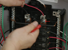
Just happened across an image of a breaker panel clearly showing the lugs bolted on (look for the arrow in the photo below) and thought I'd post it.

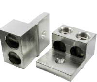
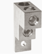
Existing Lug-> 1641652937232.png Replacement dual lug -> 1641652982492.png or 1641653258856.png

So in the load center you'd replace your single lugs with dual lugs, mains go in one and the inverter the other. The lugs are usually just bolted on. But YMMV based on the load center.

1641652853345.png
 
I've used those side-by-side dual lugs.
As I recall, in a 225A QO load center they fit fine. In 125A QO load center (which takes a smaller size main breaker), there was some interference.
Probably the up/down dual lug would be a better fit.

But for what purpose, the line-side tap?
These lugs only go on a panel without main breaker, which is protected by a breaker upstream. Inverter would need suitable breaker protecting it (probably lower amperage than breaker feeding this panel.) Still have 120% rule issue - current from breaker feeding this panel plus current from inverter available to panel busbar, and flowing through it. So 100%, no 120%, would be the limit.
 
40A PV breaker, but only operate up to 80% for continuous current, 32A inverter output x 240V = 7680W
Therefore, a number of inverters of that rating.

You're aren't likely to find a 175A main breaker. I'm aware of 200A and 150A for one particular panel I have.

"Line side tap" is one approach, another circuit taken off between main breaker and meter.
That may be accomplished with an insulation piercing connector.
There are meter socket adapters available with an extra tap. My utility PG&E offered that, but 40A max.


Ahhh... thank you. Thing is that in my case the Inverter is 60 Amp. BUT... I am glad that you shared about the line tap because that is good information to know.

Les
 
My 6kw of inverter easily covers the critical loads at my place including the A/C blower (furnace blower) (not the outside condenser) all the kitchen, including 2 chest freezers. All the lights, and receptacles on the first floor for computers, TV's internet etc. All that is covered by about 600w continuous. Kitchen draw can easily add an additional 1500w from microwave or crockpot etc.

So as long as your not stacking the well pump ontop of the water heater ontop of the air compressor you should be good. Depending on how serious your off-grid prepping is, you might consider a large propane tank for a propane water heater and propane for backup generator. Hotwater alone is a huge power consumer. (assumeing you dont go with one of the fancy new extremely expensive heat pump units)
It has occurred to me that there is a lot of marketing hype designed to give the impression that "our brand" solar system is going to abundantly supply all your needs and wants " To Infinity and beyond". :);) In fact... my Inverter in LARGE print states LIMITLESS POWER. Very impressive !!! And to further add to the impressiveness it states that it is a 12,000 watt Inverter.

What they do not mention is that your Inverter Maximum Continuous Power rating is 33 Amps @ 240 Volts. Hmmm.... seems to me that it would be much easier to sell a 12,000 watt Inverter than a 33 Amp Inverter. ? Oh... and they fogot to mention that while technically it is a 12K Inverter it only puts out about 8000 watts or 9000 max and I think that is with a grid tie.

The point is this... when I first started, because of the marketing hype, I thought I had far more Inverter than I do in reality and so I am having to adjust my expectations to the reality. I am still glad that I purchased the Inverter that I did and would even recommend this brand to others because I still think it is a good company with a good product. So what I am doing is I am downsizing the load in the shop so that it will be much lower for I need to use it in case of a grid failure. The circuit breaker for the air compressor will be left off so I can use it only when I know the load in the house is low. The beauty of the new solar systems is that they show how much power your are producing and consuming so you can learn to moniter and adjust. I am looking forward to learning all of that and I think that is one of the fun things about going solar.

And once I begin to get a handle on all of that I will look into things such as hot water tank. Who knows, I might be fine. But there are a lot of options these days including those vacuum sealed cylinders and their prices are not really all that bad considering what percentage of your utility bill is the HWT. You would get your money back in time. And thanks for the input! I have learned a lot.

Les
 
Sol-Ark inverter can process 12 kW of PV and produce 8 kW of AC, that's a good balance for battery system.
While grid connected, if battery full only 8kW of the 12kW can be harvested, but that's just "over paneling", will sustain 8kW for more hours.
Given how much cheaper PV is these days than balance of system, that isn't a bad thing to do.

Note also that 8 kW of AC is no more than 4kW on each of two 120V phases. And really "8 kVA", can drive an 8 kW resistive load but not as large a load with < 1.0 power factor, such as motors and anything with rectifiers and capacitors such as power supplies.
 
Going back a few posts, there was concerns about stepping down the main breaker to 175 amps.

That's 42,000 watts!

If that's not enough, how is a 9,000 watt Sol-ark going to cover any meaningful portion of your loads.

My Schneider XW 6848 also has a 60 amp breaker in the main panel, so I've got a 150 amp main breaker. That was no where near $250, I think it was more like $75

Also, I can program the Schneider to limit grid draw. It can be programmed for a 20 amp breaker for example. Not sure if the Sol-ark supports this feature.

The breakers that are in the house now are Bryant. Not very familiar with that brand. The one that I saw that looked like the main was something like $259.00 and probably freight. I looked online and found a guy doing an "insulated" side tap and what I like about that is that the electricity does not have to be shut off. I am going to check into that a bit more.

Les
 
Sol-Ark inverter can process 12 kW of PV and produce 8 kW of AC, that's a good balance for battery system.
While grid connected, if battery full only 8kW of the 12kW can be harvested, but that's just "over paneling", will sustain 8kW for more hours.
Given how much cheaper PV is these days than balance of system, that isn't a bad thing to do.

Note also that 8 kW of AC is no more than 4kW on each of two 120V phases. And really "8 kVA", can drive an 8 kW resistive load but not as large a load with < 1.0 power factor, such as motors and anything with rectifiers and capacitors such as power supplies.

I checked and the well pump is 3/4 H.P. and of course a capacitor start that we will need to deal with.

Les
 
I want to thank everyone who has helped along the way. After taking a bit of a break I now have the priority panel all finished and up and running on the grid through the "Inverter bypass" that we put in. I also put a "shop bypass" so that the shop normally runs on the grid. However, should a situation arise that the grid is down for an extended period of time I can simply turn off the large air compressor and put the shop on the priority panel at the flip of a switch.

So there are two main things left before I am able to start the Inverter.

1- the batteries. I have two banks of 16 lithium Ion for 48+ volts. For some reason the kit had two sets of voltage monitors??? could that be correct? While there are two banks, once they are connected they become one so I am wondering about that. (Solark 12k Inverter)

-Balancing the batteries... after looking at the youtube posted here I realized that it is very important that the batteries are balanced. So I hooked each battery bank together in parallel for several weeks only to discover that one bank was significantly higher so I have now hooked both banks together and they will likely be exactly the same charge by the end of the week. I think they will settle out at 3.31 volts. So each cell should soon be exactly the same at 3.31. Am I okay to hook them in series and let the solar charge them??? Doesnt make sense to buy a charger to top balance them when I could hook them up on a sunny day and let the Inverter do that. Thoughts???

2- The array... Here is the important one. Here is where I do not want to fry the Inverter. After looking at my panels, determining Inverter requirements, factoring in for cold days I am looking at three feeds with 10 panels, 9 panels and 9 panels fed through 6 #4 gauge wire up to the house.
  • Nominal Power (Pmpp): 325 Watts
  • Nominal Power Voltage (Vmpp): 34.36 Volts
  • Nominal Power Current (Impp): 9.32 Amps
  • Open Circuit Voltage (Voc): 42.04 Volts
  • Short Circuit Current (Isc): 9.77 Amps
  • Panel Efficiency: 18.87%
The Inverter has two inputs and at this point I want to make sure that this gets done right. With all of the solar systems going in these days I am thinking someone here has the safe answer. So 28 panels into 6 wires up to the house then down to two into the Inverter. The Inverter is looking for 175-4.25 with 450 Max.


Solark 12K Inverter
Thanks guys...

Les
 
Back
Top