diy solar

diy solar

MPP LV6548 AC Wiring Question

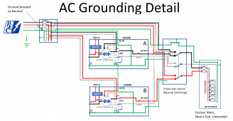
Anyone want to sanity check the below? Especially the use of the Auto-Transfer switch? Also, the auto-transfer switch I've got sitting in my Ebay shopping cart says to use an under-over voltage protector with it. But, the manufacturer doesn't sell a 3 pole anything (except the switch) ... I assume I'd use a 2 pole for each of the Lines, tying the Neutrals together? Thanks much in advance for any help ...
1665025406973.png
 
Anyone want to sanity check the below? Especially the use of the Auto-Transfer switch? Also, the auto-transfer switch I've got sitting in my Ebay shopping cart says to use an under-over voltage protector with it. But, the manufacturer doesn't sell a 3 pole anything (except the switch) ... I assume I'd use a 2 pole for each of the Lines, tying the Neutrals together? Thanks much in advance for any help ...
View attachment 115168
What do you need a auto transfer switch for? How big is your battery bank and how large is the household load?

Each LV6548 has a built in neutral switching transfer switch which enables bypass to grid when battery/solar power is not sufficient.
 
Ok, I'll do it ... any idea the reason behind that? Future work maybe?

EGC runs with live wires according to NEC. That's all there is to it. Does make some sense, for example, if you had circuits in conduit and the conduit sustained damage where the wires are crushed and not shorted to metal conduit or were in non metallic conduit.
Oh, my ... someone on that oh so long thread used the word "debacle" to describe this ... it's taken me almost all day to come to a conclusion. I'll be doing what you suggested, as I thought yours made the most sense. And, actually, hours later, coming back to this thread, I'd forgotten who'd pointed me to that discussion, so I wasn't "prejudiced" when I made my decision. I mean, Wow. Where are all the manufacturers on this? This has to be one of, if not the most common way of using these boxes. Thanks so much for posting all of this, and helping me, and all of us, out.
View attachment 115135
That is how mine will be wired, except I will run the inverter EGC's directly back to the bonded main panel and a seperate EGC to 3 pole transfer switch and on to the subpanel.
 
What do you need a auto transfer switch for? How big is your battery bank and how large is the household load?

Each LV6548 has a built in neutral switching transfer switch which enables bypass to grid when battery/solar power is not sufficient.
I don't think you need the auto switch. You can use the Manual xfer switch to directly supply grid power to your sub-panels should you need to take the LVs offline for any reason. My question is how do you isolate them from AC in? Is the feed to the manual xfer switch before or after that 60A breaker you show? If before, that's my answer (and glancing at your diagram again I just saw the 100A breaker feeding that line so nevermind I have my answer)


Ed
 
Anyone want to sanity check the below? Especially the use of the Auto-Transfer switch? Also, the auto-transfer switch I've got sitting in my Ebay shopping cart says to use an under-over voltage protector with it. But, the manufacturer doesn't sell a 3 pole anything (except the switch) ... I assume I'd use a 2 pole for each of the Lines, tying the Neutrals together? Thanks much in advance for any help ...
View attachment 115168


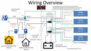
Hey on those solar panels, do you rather mean 4s2p? That is the typical wiring on the solar circuit, series first, then parallel (then you only have to combine them once in the end). Or are you really going to parallel each pair first, and string those sets in series?

My guess is you just expressed it backwards on the diagram, but just thought to check.
 
Last edited:
What do you need a auto transfer switch for? How big is your battery bank and how large is the household load?

Each LV6548 has a built in neutral switching transfer switch which enables bypass to grid when battery/solar power is not sufficient.
Battery bank is 38.4 kWH, covering one sunny day ... normal house load, with current AC unit is 54A (strangely, exactly the capacity of the two inverters in inverter mode). I'll be adding 5 mini-splits soon which should take that number down considerably, except when the central still goes on. The original plan/calcs were made to cover 90% of the energy use ... everything but high throughput loads (such as once in a blue moon I have 4 burners going on my stove). So, I'd like to get everything possible on the solar system as possible, as close to the capacity of the 54A as possible, then never have to worry about overloading it, nor the system running out of juice. Thus the auto-transfer ...
 
EGC runs with live wires according to NEC. That's all there is to it. Does make some sense, for example, if you had circuits in conduit and the conduit sustained damage where the wires are crushed and not shorted to metal conduit or were in non metallic conduit.

That is how mine will be wired, except I will run the inverter EGC's directly back to the bonded main panel and a seperate EGC to 3 pole transfer switch and on to the subpanel.
So both inverters directly back to the Main instead of tied to each other first? Somewhere in that long thread you basically showed the pic I'm showing ... did you change your design slightly? As I recall, you were talking about objectionable current between the inverters on the Ground, but that that wouldn't matter on a "single" power source, especially in metal conduit ... does sending them both directly back to the Main fix that?
 
I don't think you need the auto switch. You can use the Manual xfer switch to directly supply grid power to your sub-panels should you need to take the LVs offline for any reason. My question is how do you isolate them from AC in? Is the feed to the manual xfer switch before or after that 60A breaker you show? If before, that's my answer (and glancing at your diagram again I just saw the 100A breaker feeding that line so nevermind I have my answer)


Ed
See above for whey auto-transfer switch ... fire and forget. (My family would be really annoyed otherwise with outages as I'm trying get as much as normal use as possible running through the solar system.)

And, yep ... it's more than annoying that these boxes can't pass through more than the 60A ... thus the convoluted design ...
 
Hey on those solar panels, do you rather mean 4s2p? That is the typical wiring on the solar circuit, series first, then parallel (then you only have to combine them once in the end). Or are you really going to parallel each pair first, and string those sets in series?

My guess is you just expressed it backwards on the diagram, but just thought to check.
Yep, 4S2P is correct. Just fixed that. Thanks!
 
I don't think you need the auto switch. You can use the Manual xfer switch to directly supply grid power to your sub-panels should you need to take the LVs offline for any reason. My question is how do you isolate them from AC in? Is the feed to the manual xfer switch before or after that 60A breaker you show? If before, that's my answer (and glancing at your diagram again I just saw the 100A breaker feeding that line so nevermind I have my answer)


Ed
I just realized ... you're right, in this design, there's no need for the auto-transfer switch at 60A. I need a larger one to handle any overages ... as well as a larger CB on the main box ... let's go see if I can find one ...
 
I just realized ... you're right, in this design, there's no need for the auto-transfer switch at 60A. I need a larger one to handle any overages ... as well as a larger CB on the main box ... let's go see if I can find one ...
I would use a 150A breaker in your first panel after the service entrance direct to a manual XFER rated for that amount, run the 60A outputs from the two inverters to its other input. The output would be Teed to feed both of the subpanels.
 
  • Like
Reactions: Zwy
So both inverters directly back to the Main instead of tied to each other first? Somewhere in that long thread you basically showed the pic I'm showing ... did you change your design slightly? As I recall, you were talking about objectionable current between the inverters on the Ground, but that that wouldn't matter on a "single" power source, especially in metal conduit ... does sending them both directly back to the Main fix that?
Inverters daisy chained. There will be objectionable current between the 2 inverters under inverter power depending on balance of 120V loads.

I consider it a single power source and thus it doesn't violate NEC.

Battery bank is 38.4 kWH, covering one sunny day ... normal house load, with current AC unit is 54A (strangely, exactly the capacity of the two inverters in inverter mode). I'll be adding 5 mini-splits soon which should take that number down considerably, except when the central still goes on. The original plan/calcs were made to cover 90% of the energy use ... everything but high throughput loads (such as once in a blue moon I have 4 burners going on my stove). So, I'd like to get everything possible on the solar system as possible, as close to the capacity of the 54A as possible, then never have to worry about overloading it, nor the system running out of juice. Thus the auto-transfer ...
I think you need to look at conservation first and spend the money there. A 38.4Kwh battery will not supply a 54A/13Kw load for a day, only about 3 hours continuous. Granted, the load won't be continuous however it does show less than 3 hours of actual runtime. PV is 14.5Kw, the math just doesn't work well.

If your load continues to be that large, you would be better served with a critical loads panel powered off solar where you power the main items that are important such as fridge, freezers, lights.
 
Inverters daisy chained. There will be objectionable current between the 2 inverters under inverter power depending on balance of 120V loads.

I consider it a single power source and thus it doesn't violate NEC.


I think you need to look at conservation first and spend the money there. A 38.4Kwh battery will not supply a 54A/13Kw load for a day, only about 3 hours continuous. Granted, the load won't be continuous however it does show less than 3 hours of actual runtime. PV is 14.5Kw, the math just doesn't work well.

If your load continues to be that large, you would be better served with a critical loads panel powered off solar where you power the main items that are important such as fridge, freezers, lights.
I've got a similar system where the math doesn't really add up, but it does allow me to shave some of the electric cost. My math is worse than his as I have only 2K worth of solar connected to 20KWH worth of battery. I cycle the battery bank between 60 and 85% SOC (when I can get it that high) each day. In the worst case the 60% could feed my normal consumption for about 10-hours allowing the storm to pass and the grid to return or the ability to start the genset. If the situation is really in the toilet I can load shed in the subpanel.
 
I would use a 150A breaker in your first panel after the service entrance direct to a manual XFER rated for that amount, run the 60A outputs from the two inverters to its other input. The output would be Teed to feed both of the subpanels.
But ... that would mean I'd have to think about how much power I'm using, no? If I'm understanding you correctly(?), I'd be on solar-only with +6A backup through the inverter to the grid unless I manually switch back to the grid. I don't want to think about it and at the same time I want to max out my solar usage ... if I go over on the high use loads, the auto-transfer simply gives me back essentially what I had before going to solar. For the high amp/low use stuff, $10 a month max to pay for that from the grid is fine with me, especially so long as my 5 and 10 year olds don't have to worry every time they flip a switch ... did I understand your suggestion? Just words are difficult with this type of stuff ...
 
But ... that would mean I'd have to think about how much power I'm using, no? If I'm understanding you correctly(?), I'd be on solar-only with +6A backup through the inverter to the grid unless I manually switch back to the grid. I don't want to think about it and at the same time I want to max out my solar usage ... if I go over on the high use loads, the auto-transfer simply gives me back essentially what I had before going to solar. For the high amp/low use stuff, $10 a month max to pay for that from the grid is fine with me, especially so long as my 5 and 10 year olds don't have to worry every time they flip a switch ... did I understand your suggestion? Just words are difficult with this type of stuff ...
The LVs will "blend" grid and solar when set to SUB or SBU (Solar Utility Battery or Solar Battery Utility) mode. Unless you're going to be exceeding 6500 watts on either leg the machines would be fine. If you pull beyond that you're right and I misunderstood. I my setup I specifically excluded certain circuits due to my capability limits (wall ovens, central air, laundry, dishwasher)
 
Inverters daisy chained. There will be objectionable current between the 2 inverters under inverter power depending on balance of 120V loads.

I consider it a single power source and thus it doesn't violate NEC.


I think you need to look at conservation first and spend the money there. A 38.4Kwh battery will not supply a 54A/13Kw load for a day, only about 3 hours continuous. Granted, the load won't be continuous however it does show less than 3 hours of actual runtime. PV is 14.5Kw, the math just doesn't work well.

If your load continues to be that large, you would be better served with a critical loads panel powered off solar where you power the main items that are important such as fridge, freezers, lights.
First, thank you. I'm enjoying defending this design ... this is a great experience, as I'm finding holes that I otherwise wouldn't have thought of. I doubt that even if I'd hired a master electrician with tons of solar experience I could have gotten what I wanted. (I have a couple of contractors, right now, out front building a simple stone column for a fence, and I'm walking out every 30 minutes micro-managing them.)

Money has already been spent on conservation ... coolest water heater ever installed (heat pump, took four full days, thought it would take a day) ... five mini-split ACs sitting in my garage (the fence is to hide the mini-splits) ...

The system was designed to handle a typical single Texas sunny day in the worst heat. I looked at the expense of adding more than that, say, even two days backup, and it just wasn't justifiable costwise. The 38.4 kWH already cost $10K ... and those are non name brand batteries. Adding another single day of batteries would take 27 years to pay back, whereas the rest of the system will be paid back in 7-10 years (not including my time). Here's the daily usage numbers ...
1665167198968.png

The -.35 on the left is an approximation of the savings the mini-splits will provide.
 
Inverters daisy chained. There will be objectionable current between the 2 inverters under inverter power depending on balance of 120V loads.
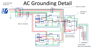
Just making sure I understand you ... is the below what you're describing? What actual physical connection will that ground use between the two boxes? The AC Out? So Box B AC-in ground attaches to Box A AC-out ground?1665178561358.png
 
Just making sure I understand you ... is the below what you're describing? What actual physical connection will that ground use between the two boxes? The AC Out? So Box B AC-in ground attaches to Box A AC-out ground?View attachment 115466
On the first inverter, you would use the EGC port on input and output. Internally the EGC ports are interconnected. As for 2 EGC's from the inverters run in the conduit to the transfer switch as shown in the diagram, I will only have one as there will only be one conduit from inverters to the transfer switch. That EGC will come from the second inverter.
 
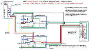
Is this method of AC wiring with a transfer switch that does not switch neutral (using a Reliance transfer switch) still best/okay to do? This image is from FilterGuy's grounding and bonding PDF. The only other question I have for it is what about the ground that runs from the transfer switch back to the main breaker box? Would it get left unattached since inverter 1 is grounded to the main box as well as the transfer switch anyways?
 

Attachments

  • Capture.JPG
    Capture.JPG
    156.2 KB · Views: 19
On the first inverter, you would use the EGC port on input and output. Internally the EGC ports are interconnected. As for 2 EGC's from the inverters run in the conduit to the transfer switch as shown in the diagram, I will only have one as there will only be one conduit from inverters to the transfer switch. That EGC will come from the second inverter.
Ok, pretty sure I "get" this now ... just for completeness, I'm posting a final design, including conduits. (Really for anyone else reading this because I know how much I hate reading incomplete instructions when I don't yet fully understand something.) Thanks again Zwy.1665262115436.png
 
  • Like
Reactions: Zwy
Back
Top