If both inverters create a neutral-ground bond in battery mode, I believe objectionable current will flow on the EGC (green wire) as shown below. Please let me know if I am missing something. Note that it has not yet been proven that both inverters do create a neutral-ground bond in battery mode in a split-phase configuration. Some people have posted that they do.
Normal neutral current is highlighted in orange. Objectionable current is highlighted in purple. The objectionable current flows to P2's neutral output connection, crosses to the EGC via P2's neutral-ground bond, flows to P1's ground connection, and crosses to P1's neutral output via P1's neutral-ground bond.
If the 120V load is drawing 10 amps, you will see 10 amps on P1's L1, 5 amps on P1's neutral, 5 amps on P2's neutral, and 5 amps on the EGC between P2 and P1. The EGC between P2 and P1 is where you want to measure the objectionable current if you are testing this scenario. Current flow on the EGC is dangerous, so be cautious when testing. The current split may not be exactly half, but I would think it would be close.
The second diagram, created by
@FilterGuy, shows the objectionable current flowing though the main panel's ground busbar and also shows the neutral-ground bonds inside of the inverters.
View attachment 86128
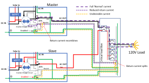
In the diagram below, the purple dashed line is the normal flow and the yellow dashed is the objectionable current.
View attachment 86130