diy solar

diy solar

MPP Solar 3048LV-MK AC Input

ArthurEld

Solar Wizard
Joined
Aug 3, 2020
Messages
2,289
Location
Palm Harbor, Florida
I am setting up a MPP Solar 3048LV-MK 48V all in one.
It has an AC charger that can output 60A.
Currently I plan to plug the AC input to a receptacle in my garage that has a 20A breaker.
Hedges warned me that this unit can use more current that 20A AC input.

I did a simple conversion -
60A X 48V = 2880W / 120V = 24A
or
60A X 60V = 3600W / 110V = 33A

I don't know which one is correct but I am sure I need more than 20A AC to get 60A DC

My electrical experience is weak.

Can someone please explain my AC input options to make 60A DC output?
I guess I might need to add a breaker to my main electrical panel.

My panel has a few 30A breakers for Dryer, Stove, Water Heater. The Dryer and Stove use special plugs and I don't know if they are 240V

I would prefer to do it in a way that doesn't require a permit. And this unit doesn't feed to grid.

I can make it work using the 20A input but I was hoping to charge my 280Ah battery at .2C
 
Both are correct. At low battery voltage 48V, a switching power supply that delivers exactly 60A will deliver fewer watts, draw less current from AC. If AC is 130V, even less.
At higher voltage of battery (before the current it accepts begins to taper off), more watts delivered. Low AC voltage, even more drawn. 110V isn't even minimum AC voltage.

Is the charger 120V or 240V input? at 120V, it's going to need at least 40A breaker, so breaker is 25% larger than load.
What are the ratings on the charger? It has some inefficiency, so may draw a bit more than the 33A you calculated (or 17A at 240V)

Probably, 240V 16A is a reasonable current draw, so a 20A 2-pole breaker could be good.
Electric dryer outlets are typically 30A. Some have neutral, most older ones just have two hots and a ground.
Electric stove typically 50A. But yours is 30A?
I put in a 20A 240V outlet for my 2 HP air compressor, which draws 11A (a 15A breaker would be better protection against stalled motor)

That link for 3048LV doesn't have full specs, but says 120VAC.
Don't know the recommended fuse/breaker, probably 40A. Maybe it can be programmed to draw less current (good for a 15A plug, 20A breaker), maybe not.
You could use an electric stove outlet if it has 4-pin and neutral wire. Just tape off the unused hot.
But then you'll just be plugging things into the inverter?

You could install a 40A or 50A breaker in your breaker panel. If you can't find a single pole, install a 2-pole and only connect one.
You could connect loads by extension cord. You could install a protected loads panel and move some circuits to it. You could get a panel which lets each load be switched.
You can also install an interlocked breaker, letting you manually turn off the main breaker and backfeed the panel. This would be handy even if you install a protected loads panel, because you can run anything in the house (within wattage limits) if you want to.
Some issues with 120V only, but can be dealt with.

280 Ah x 48V x 0.2C/120V = 22A
If you want to limit charging to 0.2C (Lead-acid?), then you need to program a reduced charge current.
15A or 16A like you could draw from a 15A outlet on 20A breaker isn't that much less.

If you have space in breaker panel, plugging in a breaker is easy enough. If you don't changing two full-size breakers for one tandem frees a slot.
You need to understand the two phases in a 120/240 panel. Best to keep each existing wire on the phase it currently connects to. Depending on wiring, if two breakers on two phases share a neutral, then putting them on the same phase will overload the neutral wire.
 
Thanks for the great reply Hedges.
Both are correct. At low battery voltage 48V, a switching power supply that delivers exactly 60A will deliver fewer watts, draw less current from AC. If AC is 130V, even less.
At higher voltage of battery (before the current it accepts begins to taper off), more watts delivered. Low AC voltage, even more drawn. 110V isn't even minimum AC voltage.

Is the charger 120V or 240V input? at 120V, it's going to need at least 40A breaker, so breaker is 25% larger than load.
What are the ratings on the charger? It has some inefficiency, so may draw a bit more than the 33A you calculated (or 17A at 240V)
This unit is 120V only
Probably, 240V 16A is a reasonable current draw, so a 20A 2-pole breaker could be good.
Electric dryer outlets are typically 30A. Some have neutral, most older ones just have two hots and a ground.
Electric stove typically 50A. But yours is 30A?
I put in a 20A 240V outlet for my 2 HP air compressor, which draws 11A (a 15A breaker would be better protection against stalled motor)

That link for 3048LV doesn't have full specs, but says 120VAC.
Don't know the recommended fuse/breaker, probably 40A. Maybe it can be programmed to draw less current (good for a 15A plug, 20A breaker), maybe not.
I checked the breakers again and the stove is 50A. I had to use a flashlight.
The documentation isn't very good. They call for a 50A breaker but in the same line it mentions the 5048 which isn't in this manual. lol
I can limit the current and I am going to try just using 15A for a while.
You could use an electric stove outlet if it has 4-pin and neutral wire. Just tape off the unused hot.
I may go for the electric stove outlet but the main panel is closer to the inverter and batteries. I don't know if it would be acceptable to use the stove breaker at the main panel.
But then you'll just be plugging things into the inverter?
Yes, the inverter has AC out with a female plug wired to it.
You could install a 40A or 50A breaker in your breaker panel. If you can't find a single pole, install a 2-pole and only connect one.
You could connect loads by extension cord. You could install a protected loads panel and move some circuits to it. You could get a panel which lets each load be switched.
You can also install an interlocked breaker, letting you manually turn off the main breaker and backfeed the panel. This would be handy even if you install a protected loads panel, because you can run anything in the house (within wattage limits) if you want to.
Some issues with 120V only, but can be dealt with.
I will think about adding a breaker but I am not going feed into the electrical system with this.
280 Ah x 48V x 0.2C/120V = 22A
If you want to limit charging to 0.2C (Lead-acid?), then you need to program a reduced charge current.
Lifepo4, I will program to use reduced current.
15A or 16A like you could draw from a 15A outlet on 20A breaker isn't that much less.

If you have space in breaker panel, plugging in a breaker is easy enough. If you don't changing two full-size breakers for one tandem frees a slot.
You need to understand the two phases in a 120/240 panel. Best to keep each existing wire on the phase it currently connects to. Depending on wiring, if two breakers on two phases share a neutral, then putting them on the same phase will overload the neutral wire.
I am going to research breakers and working on the main electrical panel. And like you say I need to look up two phases 120/240
 
Installing one, 30A single-pole breaker is best.
Do you have any available slots?
If not, take a photo of the panel with cover removed. That would let me see what could get rearranged.
What I look for in particular is whether a single cable (wires red, black, white, bare copper) has red and black connected to two separate single-pole breakers. Those are the circuits we have to be careful to not incorrectly rewire. But it can still be done.
If two single pole breakers each has its own cable (wires black, white, bare copper), then a tandem breaker can replace the two breakers, freeing up one slot.
 
After you get that working, here's something you could add later:


You will have a 30A single pole breaker in your main panel feeding the inverter.
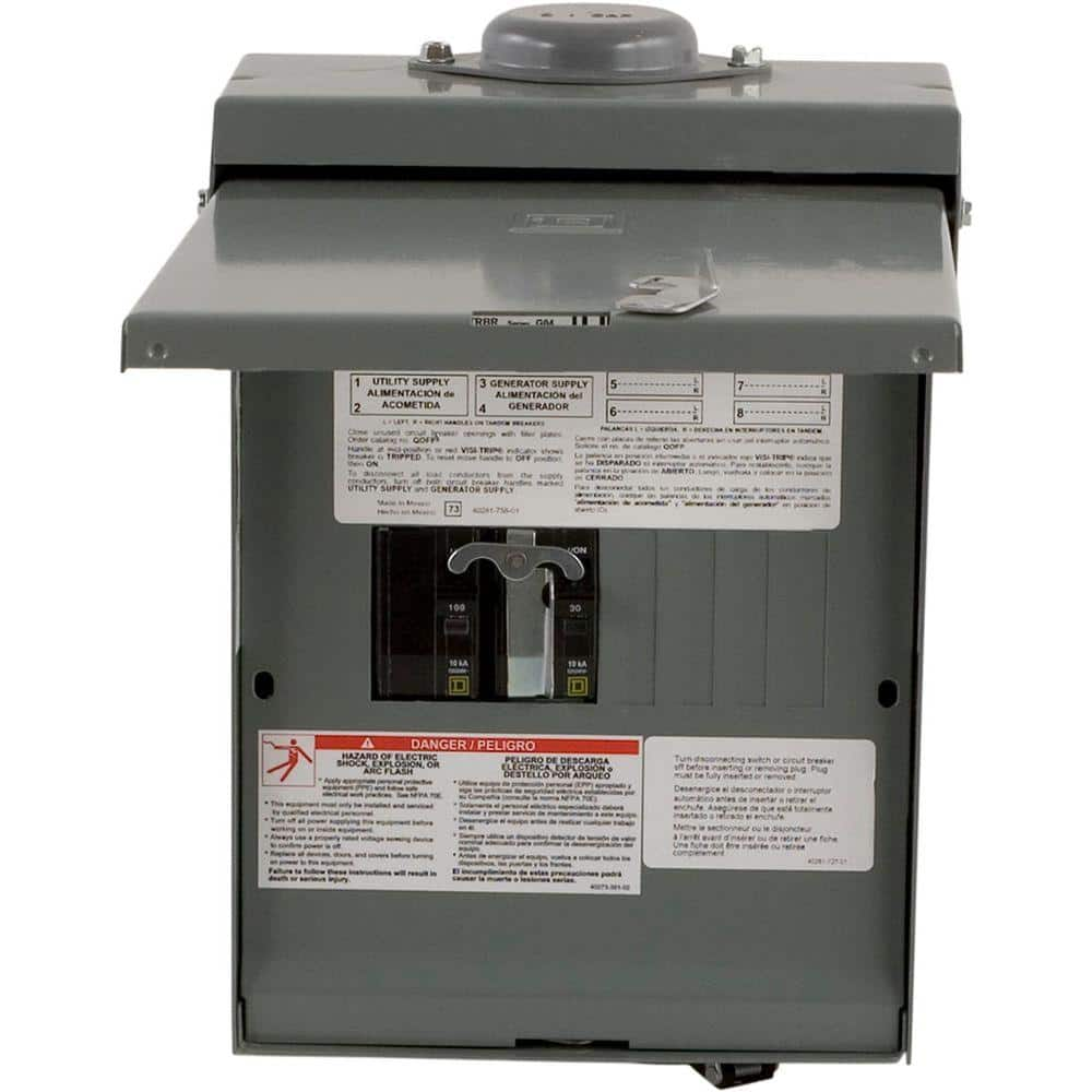
Inverter output goes to this transfer switch. (it has a twist-lock plug on the bottom for generator cord)
Another wire from main panel goes to this transfer switch (100A or less)
Move any circuits you want over to the this switch, adding breakers for them.

That will let you have protected loads (refrigerator, computer) powered by the inverter.
If inverter fails, you just flip the transfer switch and they're back on the grid.

I have my whole house (it is a sub-panel that was previously wired to main panel) on the output of my Sunny Islands.
I installed this transfer switch so if the system fails, my wife can just throw the switch to have the house direct to grid.
 
Installing one, 30A single-pole breaker is best.
Do you have any available slots?
If not, take a photo of the panel with cover removed. That would let me see what could get rearranged.
What I look for in particular is whether a single cable (wires red, black, white, bare copper) has red and black connected to two separate single-pole breakers. Those are the circuits we have to be careful to not incorrectly rewire. But it can still be done.
If two single pole breakers each has its own cable (wires black, white, bare copper), then a tandem breaker can replace the two breakers, freeing up one slot.
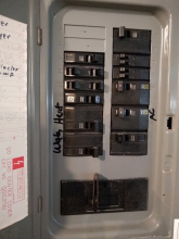
Here's my main panel.
1607444838707.png
 
After you get that working, here's something you could add later:


You will have a 30A single pole breaker in your main panel feeding the inverter.
Inverter output goes to this transfer switch. (it has a twist-lock plug on the bottom for generator cord)
Another wire from main panel goes to this transfer switch (100A or less)
Move any circuits you want over to the this switch, adding breakers for them.

That will let you have protected loads (refrigerator, computer) powered by the inverter.
If inverter fails, you just flip the transfer switch and they're back on the grid.

I have my whole house (it is a sub-panel that was previously wired to main panel) on the output of my Sunny Islands.
I installed this transfer switch so if the system fails, my wife can just throw the switch to have the house direct to grid.
I like that and I am going to have to think about it for a while. I might do something like that one day.
 
Here's my main panel.

You have two empty slots, so just stick in a 30A single pole breaker to start.

There are several tandem breakers in there. Also some singles.
You should be able to free up one more slot, but without seeing the wires I can't enumerate all of them.

Assuming the upper left breaker is 15A (I can't read it), you could replace the 15A double-pole with two tandem 15A breakers. Insert a plastic tiebar between them and it'll work like (single 15A, 2-pole 15A, single 15A)
Then you can move the circuits from two 15A single breakers on the left over to these.
That frees up 2 more slots.

Install a 100A breaker (or smaller) and that can wire to the generator transfer switch.
Then you can add protected loads.
Or move over loads presently on the main panel (that frees up slots, so the game with tandem breakers wasn't necessary.)

You already have QO, so the QO generator switch I suggested accepts the same breakers. It has 4 slots available.
If you run conduit from main panel to generator switch, you can stuff or pull out wires any time.

Your panel is indoor, so an indoor generator switch may flush-mount to wire up more nicely (if they offer that; may not due to where plug for generator is located.)
 
Thanks again for all of the great info Hedges. I'll probably have more questions later.
I will work on adding one 30A breaker for now.
 
I finally got the inverter up and running.
I'm discharging my battery by actually using the energy instead of burning it off.
That is a step in the right direction.

The next step is to set up some shelves near the main electrical panel so I can move everything over there.
Then I can connect using the 30A breaker for faster charging.

I will also get my four 100W panels connected to help with the charging.
 
After you get that working, here's something you could add later:


You will have a 30A single pole breaker in your main panel feeding the inverter.
Inverter output goes to this transfer switch. (it has a twist-lock plug on the bottom for generator cord)
Another wire from main panel goes to this transfer switch (100A or less)
Move any circuits you want over to the this switch, adding breakers for them.

That will let you have protected loads (refrigerator, computer) powered by the inverter.
If inverter fails, you just flip the transfer switch and they're back on the grid.

I have my whole house (it is a sub-panel that was previously wired to main panel) on the output of my Sunny Islands.
I installed this transfer switch so if the system fails, my wife can just throw the switch to have the house direct to grid.
I ordered this transfer switch. I thought about ordering the Reliance instead but decided to get this one for now.
 
I shut off the power and installed the 30A breaker. That was my first time inside a main panel.
I put it back together and have wire coming out with the breaker off.
Some people have covers over the live lugs coming into the panel. I will do something like something like that next time I'm in there.
 
I drained one of my batteries by plugging in a refrigerator.
I set the BMS to stop discharging at 3.0V and let it go for days.
When I noticed it shut off I didn't pay much attention. I assumed the grid power would take over running the fridge.

The BMS shut everything down. I'll remember that.
 
Part of the reason I bought this little MPP Solar all in one is so I can get a preview of the larger SolArk system I plan to install.
So, I connected the inverter to my main electric panel and I connected one circuit through the a Reliance transfer switch.

One thing I tried was to not run neutral though the transfer switch. I also only ran ground to the main panel. Since my inverter is only 120V, I only have one wire running from the inverter to the transfer switch. Ground is connected to the main panel.

SolArk says the neutral is unnecessary and ground only needs to go from the main panel to transfer switch. Reliance says to just pass neutral through the transfer switch and connect ground to main, inverter and transfer switch. And Hedges thinks there might be some kind of electrical (radio?) interference if I don't run neutral through the transfer switch.

I'm lazy so I went with the easiest (1 wire) choice first. If interference becomes a problem, I will try running neutral through the transfer switch.

The transfer switch is working with grid power. ?

I still have to connect the battery so I can use inverter power. I plan to connect 4 solar panels too.

Slow and steady wins the race.

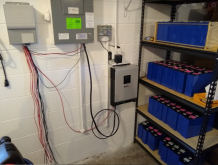
1608925664509.png
 
And Hedges thinks there might be some kind of electrical (radio?) interference if I don't run neutral through the transfer switch.

If interference becomes a problem, I will try running neutral through the transfer switch.

Not generally radio interference (though could occur with loads generating harmonics, like feeding a rectifier/capacitor input of a switching power supply)

Routing neutral through a different path is like wrapping the wire around an iron core. That makes an inductor, which will have some impedance to AC. The core is lossy, so power will be dissipated, heating the steel box and conduit. At least that's the theory.

I couldn't measure anything of interest when I did that deliberately with currents regulated by resistive loads.
Maybe that 600A commercial application I heard about heating metal red hot was carrying lots of harmonics due to feeding VFD. The higher frequency harmonics will see more impedance, and iron core losses will be greater.

So I haven't been able to prove a problem, but I always provide neutral return running along same path as hot wires.
SolArk is causing a lot of confusion by saying that the neutral and part of the ground are unnecessary. And I understand what you are saying about having neutral take a longer or completely different route. Since the inverter AC in and AC out neutrals are connected the route is very similar. But I also read something about overloading a neutral.
It is very easy for me to run neutral though the transfer switch. And I may just do that on my final SolArk installation.
 
When I do my final installation, the transfer switch will be between my service panel and the inverter.

It would be cleaner for me to run all of the wires going from the service panel to the inverter (AC in and out) through the same conduit for the transfer switch. Is there a problem with doing it that way?
 
May I ask as to how much they charge you for shipping that MPP to you? Thanks.
$130 from MPP Solar China/Taiwan. I inquired about the shipping price and they responded with the same shipping price that showed on the Alibaba page. $540 + $130 shipping = $670
It took about 10 days to arrive to Florida.
 
Last edited:
Back
Top