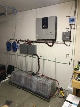
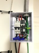
@SolarBro if I may ask a question. I have a completely off grid setup, no grid service at all. We are in an RV. For my AC Input I am using a generator, wiring a 50 AMP input plug, running wire from the plug to a 40 AMP load center, and then running from the 40 AMP load center into the AC Input on the LV5048. For the AC Output on the LV5048, I am running from the inverter to a 100 AMP main lugs load center with a 50 AMP service breaker. From the 50 AMP service breaker I am running to a 50 AMP outlet.
I will plug in a 50 AMP RV cable from the 50 AMP outlet coming from the Inverter into the 50 AMP input on the RV.
There obviously is no grounding rod yet, so I will install one of those next to the RV. My question is, because there is no grid service Main panel with grounding, how do I go about grounding the whole system? I understand I need to jump the AC In and AC Out neutrals on the LV5048, but I am not sure what point in the system I should introduce the ground wire from the grounding rod.
I am also confused about the green ground screw that came with both panels to ground the box. I have read that you only use that in the Mains panel, but neither one of my panels seems to be the mains panel as several people have said the LV5048 is considered the mains panel.
Thanks in advance for any help.