diy solar

diy solar

MPP Solar LV6548 AC Input and Output Main Panel and Sub Panel Wiring

SolarEddie

New Member
Joined
Sep 19, 2022
Messages
21
Hello all, I’m trying to understand the wiring diagram and circuit breaker requirements from the main breaker to 5 LV6548 inverters AC inputs, then the 5 inverters AC output to a sub panel?

Inverters 1-3 are in 1st phase, inverters 4-5 are in 2nd phase.

Plan is to program LV6548’s to provide power by priority: 1) 19.6kW rooftop solar; 2) 41kW batteries; 3) grid.

What I have gathered from other threads, for split phase with two units I would install a 60a 2-pole circuit breaker on main panel and run one hot to 1st phase inverter and one hot to 2nd phase inverter. Then I would run AC output for both inverters to the sub panel to another 60a 2-pole circuit breaker.

Not sure how to configure this for 5 inverters?

Also, intermittently to reduce idle energy consumption and when high demand is not necessary, the plan is to turn off inverters 2-3 of 1st phase and inverter 5 of 2nd phase to run system with 2 units in split phase.

I have not purchased the sub panel yet, the main panel is a Square D Homeline, so any input on sub panel models with 40 spaces or more in the same line would be appreciated so I can recycle all the current circuit breakers by transferring them to the sub panel. I’ve also considered a “smart” sub panel (i.e. Lumin) for load management. Experience in this area is appreciated as well.

Thanks for any guidance.

Maybe have an input breaker box and and output breaker box, using a pair of double pole 60a snapped into the buses, so on the input side, pulling from each breaker set, and on the output, feeding to each 60a breaker set. Could also take out the bridges (rods) if you want the double pole switch levers to operate independently... Or if you can find single pole 60a, not sure if those are available.
 
I’m thinking that you may have a problem running 5 inverters for split phase. I may be wrong but I thought that you needed even numbers for that. 4 inverters would still be a monster setup with a spare.
 
If you want to scale down power by turning off units you may need to manually disconnect the communication cables and tell the master unit that it’s slave count has change. That’s going to be a hassle. For longevity I’d leave them on. Turning things on and off can cause more stress. If it’s standby power drain than get a few extra panels. Each inverter draws 45 watts at idle.
 
Maybe have an input breaker box and and output breaker box, using a pair of double pole 60a snapped into the buses, so on the input side, pulling from each breaker set, and on the output, feeding to each 60a breaker set. Could also take out the bridges (rods) if you want the double pole switch levers to operate independently... Or if you can find single pole 60a, not sure if those are available.
Thanks for the feedback. I'm probably missing something, but would 3 60a 2-pole circuit breakers on the main panel achieve this? Two of them would provide 4 hot leads to AC input on 4 inverters, the last one I would only use 1-pole of the 2-pole breaker to provide input to the 5th inverter. Then mirror the same output onto the sub panel? Sorry if I'm misunderstanding.
 
If you want to scale down power by turning off units you may need to manually disconnect the communication cables and tell the master unit that it’s slave count has change. That’s going to be a hassle. For longevity I’d leave them on. Turning things on and off can cause more stress. If it’s standby power drain than get a few extra panels. Each inverter draws 45 watts at idle.
I have tested output voltage by shutting any number of units off so long as one unit is on from the 1st phase and one unit is on from the 2nd phase. Will continue to output 240v in split phase. My concern is that depending on how AC input/output is configured, would this impact operation on grid power. My assumption is that if I'm running AC input/output on a separate breaker for each inverter then powering down one or multiple units wouldn't have an impact so long as one in the 1st phase is still on and one in the 2nd phase is still on.

Btw, I have nearly 20kW of solar panels across 45 panels. I might be being overly conservative with power, but I want to minimize idle power drain as much as possible. The only time I really anticipate using full power is with heavy house usage and 2 EVs charging. Ultimately the plan is to use "smart" load balancing software for the limited times when I have peak loads like this.
 
Last edited:
I’m thinking that you may have a problem running 5 inverters for split phase. I may be wrong but I thought that you needed even numbers for that. 4 inverters would still be a monster setup with a spare.


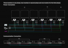
Well the more common approach on the topologies they show in the manual might be with 3-phase setups when one might desire an asymmetrical approach:

1663615946078.png

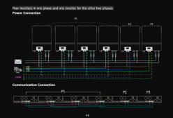
or:


1663615971575.png


It could also be simple a single-phase, split-phase with only a P1 and a P2, and lop-sided, just depends on how you set the degrees on them like 120° or 180°, or whatever.
 
Well the more common approach on the topologies they show in the manual might be with 3-phase setups when one might desire an asymmetrical approach:

View attachment 112581

or:


View attachment 112582


It could also be simple a single-phase, split-phase with only a P1 and a P2, and lop-sided, just depends on how you set the degrees on them like 120° or 180°, or whatever.
@Samsonite801, please see link above from MPP Solar (https://www.mppsolar.com/v3/catalogs/supplement parallel diagram to SPLIT PHASE LV.pdf). So long as you have the communication connections configured correctly and as you note it programmed correctly in the software, they will run anything from 2-8 units in split phase.
 
@Samsonite801, please see link above from MPP Solar (https://www.mppsolar.com/v3/catalogs/supplement parallel diagram to SPLIT PHASE LV.pdf). So long as you have the communication connections configured correctly and as you note it programmed correctly in the software, they will run anything from 2-8 units in split phase.

Yeah that's exactly what I was expecting, because I've read these sections, I just never wired it up myself yet and programmed it. I went and saw my neighbor's EG4 6500EX's though yesterday, and basically, if you want P1 or P2 you just set whichever ones on the side you want them on and it works.
 
Thanks for the feedback. I'm probably missing something, but would 3 60a 2-pole circuit breakers on the main panel achieve this? Two of them would provide 4 hot leads to AC input on 4 inverters, the last one I would only use 1-pole of the 2-pole breaker to provide input to the 5th inverter. Then mirror the same output onto the sub panel? Sorry if I'm misunderstanding.

For which side, input or output? Those need to stay isolated. But yeah, each hot in or out of the inverter needs its own single pole (or half of a double-pole) breaker.

NOTE:
Double-pole breakers, can remove the little bar in between the toggles, if independant switching is desired..
 
Yeah that's exactly what I was expecting, because I've read these sections, I just never wired it up myself yet and programmed it. I went and saw my neighbor's EG4 6500EX's though yesterday, and basically, if you want P1 or P2 you just set whichever ones on the side you want them on and it works.
It's really a great design. I figure also, let's say a few years down the road, one unit goes bad, I can just reprogram the remaining units to suit my needs.
 
The only problem I can think of, is when you shut off some inverters, those internal ATS relays will release (inverter in bypass), so you need to make sure and also turn off those particular breakers (at least on the outputs for sure), when they are switched off, so they are completely out of the loop..

Meaning, you don't want your input AC to bypass into your output panel while other inverters are on.
 
For which side, input or output? Those need to stay isolated. But yeah, each hot in or out of the inverter needs its own single pole (or half of a double-pole) breaker.

NOTE:
Double-pole breakers, can remove the little bar in between the toggles, if independant switching is desired..
I was thinking both, this configuration on input and output side. It would eat up more spaces but I have the extra. I could also remove all the bars so each hot input/output is on an independent circuit. Just not sure if this is the "right" way to set them up.
 
The only problem I can think of, is when you shut off some inverters, those internal ATS relays will release (inverter in bypass), so you need to make sure and also turn off those particular breakers (at least on the outputs for sure), when they are switched off, so they are completely out of the loop..
Wow! Very good point. If it allows bypass power from any power source that would not be good. Thanks for the heads up.
 
I was thinking both, this configuration on input and output side. It would eat up more spaces but I have the extra. I could also remove all the bars so each hot input/output is on an independent circuit. Just not sure if this is the "right" way to set them up.

What is 'right'... To me I guess (in the USA myself), right means NEC, because I don't want some inspector to ever condemn my home.
 
Wow! Very good point. If it allows bypass power from any power source that would not be good. Thanks for the heads up.

Which brings up a question for me too here. How does this kind of multi-inverter topology behave, when just doing normal booting sequence? (with the bypass behavior of each inverter)

I guess you'd leave all the input AC breakers off first, (optional: turn on the AC output breakers?) then power on the slaves, then the master, turn on output breakers (or turn on output breakers prior to power-on inverter sequence), then add AC breakers' input last...

There is some amount of this I am wanting to think about myself, since I do have 4 of the LV6548, coming up for my install very soon. I'm pretty close to getting my building installed.
 
Last edited:
Good point. How would I go about looking up the "right" way to wire this based on the NEC?


Here hehe:


I usually just google about specific NEC related concerns... And after years, you start to remember more and more of what you had researched. Basically to start to remember the points that matter most.
 
Which brings up a question for me too here. How does this kind of multi-inverter topology work, when just doing normal booting sequence? (with the bypass behavior of each inverter)

I guess you'd leave all the input AC breakers off first, (optional: turn on the AC output breakers?) then power on the slaves, then the master, turn on output breakers, then add AC breakers' input last...

There is some amount of this I am wanting to think about myself, since I do have 4 of the LV6548, coming up for my install very soon. I'm pretty close to getting my building installed.

I'm actually off-grid with my setup anyways, so I was going to have an AC input circuit only fed by the generator input bus (turned off at input breaker box most the time), and I am actually adding standalone AIMS 48v battery chargers (one for each leg of generator), which would be my supplemental battery charging anyways, so for me, this wouldn't be a concern about input AC shorting into the output AC bus, since I would only be using the input AC circuit on the LV6548s for ultimate failsafe in case my standalone 48v battery chargers failed.
 
Back
Top