diy solar

diy solar

MPP Solar LV6548 AC Input and Output Main Panel and Sub Panel Wiring

Here hehe:


I usually just google about specific NEC related concerns... And after years, you start to remember more and more of what you had researched. Basically to start to remember the points that matter most.

Also another hint about NEC, is that it's mostly related to safety, so obvious things are protecting circuits/wires, from overcurrent, meltdown/fire hazards (grounding too). They do offer insights and recommendations as well, like for example with voltage drop, and best practices, but if it's not a safety issue, then it may be a best practice recommendation based on best performance (and not a NEC hard requirement)...

Afterall, NEC is a division of the NFPA (National Fire Protection Association)...
 
Last edited:
Also another hint about NEC, is that it's mostly related to safety, so obvious things are protecting circuits/wires, from overcurrent, meltdown/fire hazards.

Afterall, it is a division of the NFPA...
Similar to you, mine is mainly an off grid system with no back feed to grid, but when I learned you can program the inverter to prioritize power using the internal ATS (1) solar; 2) batteries; 3) grid) I thought why not have grid setup as the third priority power source, just in case. Obviously this now adds a layer of complexity...

I work in tax and similarly, whatever position you take on a tax issue needs to be backed up by the applicable Federal or local tax law. Half the challenge is knowing which law to apply and how to interpret it. Without NEC experience I'm a little lost as how to even lookup the correct section in the NEC that applies to this particular situation?
 
Which brings up a question for me too here. How does this kind of multi-inverter topology behave, when just doing normal booting sequence? (with the bypass behavior of each inverter)

I guess you'd leave all the input AC breakers off first, (optional: turn on the AC output breakers?) then power on the slaves, then the master, turn on output breakers (or turn on output breakers prior to power-on inverter sequence), then add AC breakers' input last...

There is some amount of this I am wanting to think about myself, since I do have 4 of the LV6548, coming up for my install very soon. I'm pretty close to getting my building installed.
The way I've been operating throughout my testing phase which is how a Will Prowse video and the MPP Solar manual suggest commissioning:
1) Turn on battery-to-inverter circuit breakers
2) Turn on batteries, allow to boot
3) Turn on inverters one at a time (if you wait too long between inverter startup it gives you an error code and turns itself off)
4) Turn on circuit breakers in the combiners boxes to the solar panels

I'm assuming grid power is treated like another power source like solar, so I assume you want to turn on the main panel circuit breaker after steps 1-3 above have been completed.

Turning off the system is just repeating the steps above in the reverse sequence.

Yeah I figured that too. My concern might be then, say one inverter fails in a way where the whole thing just turns off (loses power, board fries, whatever)? Now the ATS relay inside it relaxes, and goes to bypass, then AC input connects to the AC output bus, and you have 2 unsynced sine waves trying to operate on the output, which eventually (if not immediately) being out of sync and shorting all the other inverters and tripping them in a cascading fashion which may or may not pop all the other breakers on the output bus, might just trip the inverters, or might trip the AC input breaker on the bypassed inverter, who knows hehe...

Oh well, good thing I won't have to deal with that potential scenario on mine...
 
Last edited:
Similar to you, mine is mainly an off grid system with no back feed to grid, but when I learned you can program the inverter to prioritize power using the internal ATS (1) solar; 2) batteries; 3) grid) I thought why not have grid setup as the third priority power source, just in case. Obviously this now adds a layer of complexity...

I work in tax and similarly, whatever position you take on a tax issue needs to be backed up by the applicable Federal or local tax law. Half the challenge is knowing which law to apply and how to interpret it. Without NEC experience I'm a little lost as how to even lookup the correct section in the NEC that applies to this particular situation?

Yeah hehe, similar to tax law, in addition to NEC, you have local county and city codes, and the power company requirements if applicable, so my rule, is try to do the diligence as best I can, then go out of my way to make it look very professional, well thought out and pretty, then schedule the appointment with the inspector (if it needs to be inspected), schedule it on a Friday afternoon when the guy just wants to get his last inspection in and get out of there for the weekend, and he probably won't nit pick it anyways. If he does, just fix the things he says, and get the final on it.
 
Yeah I figured that too. My concern might be then, say one inverter fails in a way where the whole thing just turns off (loses power, board fries, whatever)? Now the ATS relay inside it relaxes, and goes to bypass, then AC input connects to the AC output bus, and you have 2 unsynced sine waves trying to operate on the output, which eventually (if not immediately) being out of sync and shorting all the other inverters and tripping them in a cascading fashion which may or may not pop all the other breakers on the output bus, might just trip the inverters, who knows hehe...

Oh well, good thing I won't have to deal with that potential scenario on mine...
Hoping to resolve this with out learning the hard way. When I thought it would be a great idea to add grid power to the mix I didn't realize the complexity I was adding! o_O
 
But to some of your other concerns relating to what is the right way...

I think from other LV6548 cabling posts, we've established that 60a breaker is what is needed on both inputs and outputs. 4 AWG cable is the largest you can fit into the input/output connector lugs (plus the manual indicates to use 4 AWG cable) etc...


So 60a breaker (for each inverter hot) stays within the 80% rule with 4 AWG cable, etc..


The other item to think about is how multiple LV6548s each have their own N-G bond in them which can cause issues. Try to find those posts. It seems people would break all the N-G bonds except for the master inverter, or else break all the N-G bonds in all of them and move N-G bond to the output breaker panel (NEC requires the use of only one N-G bond, and have it usually as close to the power source as possible).
 
Last edited:
But to some of your other concerns relating to what is the right way...

I think from other LV6548 cabling posts, we've established that 60a breaker is what is needed on both inputs and outputs. 4 AWG cable is the largest you can fit into the input/output connector lugs, etc...

The other item to think about is how multiple LV6548s each have their own N-G bond in them which can cause issues. Try to find those posts. It seems people would break all the N-G bonds except for the master inverter, or else break all the N-G bonds in all of them and move N-G bond to the output breaker panel (NEC requires only one N-G bond, and have it usually as close to the power source as possible.
Yes on the 60a 2-pole 4 awg.

Regarding inverter N-G bonds, they do, and have to be dealt with. From what I've read, all LV6548 internal N-G screws need to be removed except the one primary unit. The only N-G bonds should be in the lead inverter unit and the main panel. The sub panel will have a neutral bond and ground bond with the main panel directly.
 
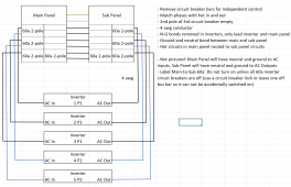
Here's what I'm thinking for AC input from grid for 5 inverters. Feedback appreciated:

1663723311463.png
 
Last edited:


Seems about right.. That's about how I was basically imagining it too.

One potential idea. On the main breaker panel, the 60a breaker (bottom right), feeding the sub panel, could maybe go right to the main bus bar feeds in the top of the sub panel (assuming you get a sub panel which doesn't have a main breaker). Then you could just have one switch to flip to connect the 2, it only needs the one 60a to protect the wire... And remember it only holds 60a, which is not the sum of what your inverters will be providing the sub panel. If you wanted full power capacity for your separate bypass, you could use a large AWG bypass wire and larger breaker to feed it while inverters are out of the loop (that is more inline with the full output of your inverters).

Technically you wouldn't even need an interconnect for bypass, since the inverters will go into bypass when turned off. You could leave one in the wall, in case you sold the house and wanted to wire in bypass circuit later.

I guess it depends on how you want to do it. But that is the idea.
Appreciate the feedback. Some good considerations. Would also free up a couple of spaces. If it came to selling and I wanted to keep the system I could also reverse the circuits from the sub panel and Route them back into the main panel. Lots of options.
 
Appreciate the feedback. Some good considerations. Would also free up a couple of spaces. If it came to selling and I wanted to keep the system I could also reverse the circuits from the sub panel and Route them back into the main panel. Lots of options.

Have a look at this video (ignore that they're using Solark inverters), just highlighting the wiring methodology of parallel AC circuits, and his bypass breaker, how it has a physical interlock on it, so it cannot be accidentally turned on.

I started the video here at the 3:00 mark, but you can bump it back a bit if you need to later if you want to see more context:


The overall video is very insightful from an installation point of view anyway...
 
Last edited:
Have a look at this video (ignore that they're using Solark inverters), just highlighting the wiring methodology of parallel AC circuits, and his bypass breaker, how it has a physical interlock on it, so it cannot be accidentally turned on.

I started the video here at the 3:00 mark, but you can bump it back a bit if you need to later if you want to see more context:


The overall video is very insightful from an installation point of view anyway...
Thanks for the video. I like the custom interlock, i am definitely going to have a mechanical safety precaution for bypass, I might use that. I watched the whole video, actually a lot of similarities to what I have, some other stuff I learned from it. My biggest problem now is finding a Square D 200a 40 space outdoor load center. Didn’t know there was such a shortage. Called every supply store in the country. Crazy.
 
Thanks for the video. I like the custom interlock, i am definitely going to have a mechanical safety precaution for bypass, I might use that. I watched the whole video, actually a lot of similarities to what I have, some other stuff I learned from it. My biggest problem now is finding a Square D 200a 40 space outdoor load center. Didn’t know there was such a shortage. Called every supply store in the country. Crazy.

Check eBay too...


I bought my box from a good seller on there...
 
Check eBay too...


I bought my box from a good seller on there...
The unicorn seems to be an outdoor. I’ve been searching/watching eBay, Craigslist, Offer Up, and Facebook marketplace, contacted every seller on Google... The only outdoor box with 40 spaces I found is a metered one (slap a meter socket cover over it) but the guy is profiteering wanting $600 for a $280 load center.
 
Back
Top