diy solar

diy solar

Mppt Bluesolar on Lfp batt. Bad charging

f1991

New Member
Joined
Aug 29, 2022
Messages
33
Hello community. I come to you because 6 weeks ago I changed my agm battery to a lifepo4 and the mppt has since used to switch to Float when the battery is not full.

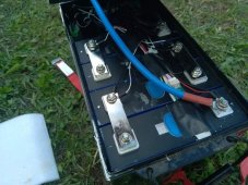
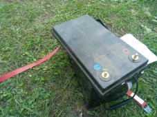
I bought the 230ah battery from an individual who built them himself for use on a motorhome, so with a Bluesolar 100/30 mppt.

The problem was presented for the first time in factory settings wheel number 7. So I bought a ve.direct cable and carried out several test settings but the problem persists. Example today :
absorption 14v and float 13.40 settings re-bulk 0.11v: 3 hours of bulk then switch directly to the float

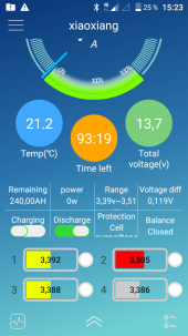
Basically it's been since I have this battery that I have never managed to fully charge it, except yesterday with the following settings: absorption 14.20 and float 13.60v, however arrived at 100% of the battery the mppt remained in absorption and created an overvoltage on one of the cells (3.92v)
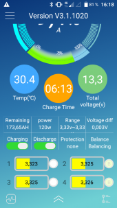
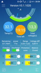
If I manage to go up to 100% charge (13.3v) the mppt does not cut and in this case remains in absorption. This creates an overvoltage on cell number 2. Moreover, even after the security lockout of the bms the mppt remains in absorption.
The BMS is a JBD 150A

I unfortunately tried to lower the absorption to 13.80v which results in an immediate switch to absorption at sunrise and causes a little later the switch to Float while the battery is at a fairly random percentage (the mppt has already gone to Float at 40% battery capacity).
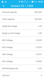
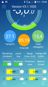
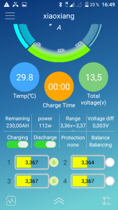
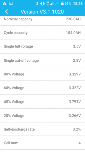
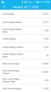
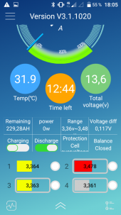
I post some pictures of my bms settings.

I need you help, the winter is coming and im 100% dependent on solar

Thanks for any help or any tips for résolve this problem. Peace!
( This post is translated to french sorry for syntax errors)

Solar panel : 2*240w BPSolar 24v
Victron mppt Bluesolar 100/30
Bms JBD 150A for 4 cells "grade a+"
 

Attachments

  • Screenshot_20220827-152636.png
    Screenshot_20220827-152636.png
    48.4 KB · Views: 14
  • Screenshot_20220827-152613.png
    Screenshot_20220827-152613.png
    54.8 KB · Views: 14
  • Screenshot_20220824-200440.png
    Screenshot_20220824-200440.png
    207 KB · Views: 14
  • Screenshot_20220824-180518.png
    Screenshot_20220824-180518.png
    208.2 KB · Views: 14
Last edited:
Change the cell and pack overvolts to protection levels, cell 3.65, pack 14.6. Release values 3.50, 14.0.
Charger, absorbtion volts 14.2, float 13.5 absorbtion time 15 min.
If you experience charge cut off due to the cell Imbalance, lower the absorbtion volts.

Mike
 
Last edited:
Change the cell and pack overvolts to protection levels, cell 3.65, pack 14.6. Release values 3.50, 14.0.
Charger, absorbtion volts 14.2, float 13.5 absorbtion time 15 min.
If you excellent cut off due to the cell Imbalance, lower the absorbtion volts.

Mike
Thanks Mike! I put the parameters that you recommended to me but something strange happened. the battery went from 47% to 75% charge! the voltage remained at 13.3v but the battery Indicate now 175ah whereas I was around 100ah just before the change.
 

Attachments

  • Screenshot_20220829-161825.png
    Screenshot_20220829-161825.png
    211.8 KB · Views: 6
  • Screenshot_20220829-164627.png
    Screenshot_20220829-164627.png
    48 KB · Views: 6
The SOC reading can do strange things at times with the JBD BMS.
13.3 volts, assuming its not under charge, is somewhere between 70 and 90 % SOC, so the 75% seems valid.
There is a 'reset capacity ' option in the app.
After a full charge cycle and a small discharge current to remove 'surface' charge the battery will read around 13.35 volts.

Mike
 
Alright, I'll try to do a full charge with the settings you gave me. I hope it will solve the charging problems and the communication between the bms and the mppt. Thanks a lot

In the options, I read that a cell is full at 3.5v, so the battery should not be at 14v at 100% charge?

I will look at this reset capacity option thanks for the tips.
 
Ive made a "reset capacity" at 100%, but my cells is at ~3.35v, shouldn't the cells be at 3.5v at 100% charge?
 

Attachments

  • Screenshot_20220904-134244.png
    Screenshot_20220904-134244.png
    212.4 KB · Views: 3
LFP Working Voltage is 3.000-3.400 Volts per cell.
Change the Charge profile to Bulk/Absorb Charge at 13.7V (3.425 Volts per cell) and float at 13.6V (3.400 volts per cell)

- Overvoltage to 3.510
- Overvoltage Release to 3.475
- Undervoltage 2.8 OK
- Undervoltage release 2.9V
- Pack overvoltage 14.4 (3.51Vpc)
- Pack overvoltage Release 13.9V (3.475Vpc)
- Pack Undervoltage 11.0V (2.750Vpc)

During a deep discharge (surge pull) the Voltage Sag could cause a cutoff and that needs to be accounted for.
Also if you have a heavy load going AND have charge input from SCC and the Heavy Load stops, there can be a momentary Spike tripping a Hi Volt disconnect. This is why there are delays.

BTW EndAmps/Tailcurrent for the 230AH Battery: 230 x 0.05 =11.5A. Once the battery is taking only 11.5A or lower, it has reached full Absorbtion (CC/Constant Current) and can change to Float (Constant Voltage/Variable Current). CC will only charge LFP to 95% then CV takes care of the rest as the amps taken decrease while the cells are saturating to the set voltage.
 
Thanks Steve, i will test your setting tommorow for a New charge cycle.
The mppt is still on bulk at the moment i take the picture. ( Mppt setting : absorption 14.2v and 13.5 for float)
victronConnect says 13.94v / 11a bulk state

Édit : still on bulk state After 1hour... I realy dont understand this mppt, why it doesnt match with the battery levels...
 

Attachments

  • Screenshot_20220904-164926.png
    Screenshot_20220904-164926.png
    208.3 KB · Views: 7
Last edited:
Thanks Steve, i will test your setting tommorow for a New charge cycle.
The mppt is still on bulk at the moment i take the picture. ( Mppt setting : absorption 14.2v and 13.5 for float)
victronConnect says 13.94v / 11a bulk state

Édit : still on bulk state After 1hour... I realy dont understand this mppt, why it doesnt match with the battery levels...
Any help? I have the same problem with Steve's settings.... Today on Float at 76%...
 
Quite often, what the SCC sees as Voltage at it's Terminals and what is at the Battery Terminals is different, there is always some Line Loss. Every connection, lug, fuse/breaker adds a bit of loss. It is cumulative so the more things in between the more loss you will get. This is where we get into Calibration & Compensation, to correct for any variations - Same applies to the Inverter.

Assume for a second that the Battery itself is at True 13.0V and with losses the Inverter sees 12.7, that 0.3V difference could result in a premature Low Volt Shutdown on the inverter if it is set shutdown at 12.8. The inverse with the SCC happens as well... Assume it sees 13.5V coming out but the battery is only getting 13.2 and the SCC is set to goto FLOAT @ 13.7 it will switch prematurely and the battery will never get there.

I must say, I am NOT Familiar with your BMS ! I used Chargery BMS' and have now converted all of my battery fleet to JK-BMS with Active Balancers so I am not familiar with the JBD nuances and quirks (they all have them).

I would suggest you check that all your connections are clean & tight, then with a DVOM check the voltage at the SCC Terminals, then again at the battery terminals and see how much of a difference there is, don't forget to check your inverter too. LFP, unlike Lead Acid Based batteries, IS Millivolt & Milliamp sensitive where Lead is "Brute Force" tech in comparison.

I have to say that the JBD software having it's settings for SOC is odd and I am not sure how they work that out. Given that LFP has a Very Flat curve from 3.000-3.400 and 50% is 3.200, which makes 3.100=25% and 3.300=75% (theoretically)
 
Figure it out F1991?
Hi,
I tried a lot of settings with or without the 230v converters and it always goes to Float at 3.20 or 3.30.
I also tried disconnecting the solar system and using only the DC/DC orion and I have the same problem with the orion switching to Float when the cells are not full.

Is it possible that this proves that the BMS is faulty since it clearly communicates badly with the Victron equipment?

Thanks for all informations you gave me. Peace
 
Last edited:
Quite often, what the SCC sees as Voltage at it's Terminals and what is at the Battery Terminals is different, there is always some Line Loss. Every connection, lug, fuse/breaker adds a bit of loss. It is cumulative so the more things in between the more loss you will get. This is where we get into Calibration & Compensation, to correct for any variations - Same applies to the Inverter.

Assume for a second that the Battery itself is at True 13.0V and with losses the Inverter sees 12.7, that 0.3V difference could result in a premature Low Volt Shutdown on the inverter if it is set shutdown at 12.8. The inverse with the SCC happens as well... Assume it sees 13.5V coming out but the battery is only getting 13.2 and the SCC is set to goto FLOAT @ 13.7 it will switch prematurely and the battery will never get there.

I must say, I am NOT Familiar with your BMS ! I used Chargery BMS' and have now converted all of my battery fleet to JK-BMS with Active Balancers so I am not familiar with the JBD nuances and quirks (they all have them).

I would suggest you check that all your connections are clean & tight, then with a DVOM check the voltage at the SCC Terminals, then again at the battery terminals and see how much of a difference there is, don't forget to check your inverter too. LFP, unlike Lead Acid Based batteries, IS Millivolt & Milliamp sensitive where Lead is "Brute Force" tech in comparison.

I have to say that the JBD software having it's settings for SOC is odd and I am not sure how they work that out. Given that LFP has a Very Flat curve from 3.000-3.400 and 50% is 3.200, which makes 3.100=25% and 3.300=75% (theoretically)

Thank you for your answer, I just understood what you are explaining to me. English is not my language at all so I take time to understand.
The volt loss lead is a good lead I think.
Everything is wired directly. from the solar charger to the battery.
I just have a fuse on the DC/AC but I tried leaving it off and the problem persists
I will check if the cables are thick enough, but normally yes, I never had problems with my old AGM batteries for more than 7 years.

For the moment the transition to Lifepo4 was a very bad idea and I regret having changed
I think it is impossible to solve this problem so I hesitate between buying a new mppt or a new bms
 
Last edited:
hi, i had another problem today. the mppt remained in bulk while the battery has been full for a long time.
I noticed that the BMS is put in safety for the cell overvoltage, the mppt is put in Absorption position at the same time. If it helps you to understand my concerns. Please help me, the winter is coming soon.
 

Attachments

  • Screenshot_20220926-152330.png
    Screenshot_20220926-152330.png
    204.1 KB · Views: 1
You said you got this setup second hand?

I would take it apart and top balance it.

That should have been the first the suggestion honestly.
 
You said you got this setup second hand?

I would take it apart and top balance it.

That should have been the first the suggestion honestly.
Hi, thanks for your answer.
I bought the battery new normally.
When you say balance, do you mean recharge the cells one by one?
If that's right, I only have 12v chargers in the RV.

I will open it to try to see if it is really 240ah cells already because finally I have a doubt.
 
Hi, thanks for your answer.
I bought the battery new normally.
When you say balance, do you mean recharge the cells one by one?
If that's right, I only have 12v chargers in the RV.

I will open it to try to see if it is really 240ah cells already because finally I have a doubt.

I'm assuming you bought diy battery made from individual cells? Got a picture of it ?


Check out this video....


I'm assuming you bought diy battery made from individual cells? Got a picture of it ?


Check out this video....


Thanks for the video I will try to translate it little by little. I don't understand English well, I speak French.

I attach pictures of the battery after opening.
They are LF230 cells. Impossible to read the QR to know the origin. All the cells are currently at 3.320v (measured with a voltmeter)
 

Attachments

  • 65252493d51525475ada7ac4ee6437af.0.jpg
    65252493d51525475ada7ac4ee6437af.0.jpg
    50.7 KB · Views: 9
  • 6d394e55be908db3557f6e6ba9726ed4.0.jpg
    6d394e55be908db3557f6e6ba9726ed4.0.jpg
    33.3 KB · Views: 9
  • efa00d1e251239a5bf947766975b0a4b.0.jpg
    efa00d1e251239a5bf947766975b0a4b.0.jpg
    37.3 KB · Views: 7
  • 295d86d01f5c004dc92d8673812fec78.0.jpg
    295d86d01f5c004dc92d8673812fec78.0.jpg
    75.3 KB · Views: 9
This is a CONCERN, such heat discoloration is NOT a good sign, looks scorched (burnt) from overheating.
Cells appear to be EVE 230AH.
Try to take a clear photo of the QR Codes and one of us can decode it. Alternatively, the Google Play Store has a "LiFePoQR Battery QR scanner". that will give you the details.

1664289301242.png
 
Ah, I can understand the language barrier issue.

This page and document are absolutely outstanding.


I would for sure top balance this setup. take it apart and wire the cells all in parallel. I bet it wasn't originally and it's likely the root of your problem. But I'm new to this and hopefully someone with more experience can weigh in.

Then you get a DC power supply - set it to exactly 3.65....set with a digital voltmeter. Then let it go until the Amps in are zero and the V rises to 3.65.
 
Back
Top