diy solar

diy solar

Mppt epever duoracer readings?

Pusscat

New Member
Joined
Mar 21, 2023
Messages
6
Location
Uk Devon
Hi, bit of a newbie enthusiast here…
I have a Motorhome with a Panasonic 245 HIT panel, 2 x efb 100amp hr each leisure batteries and an EPever duoracer DR3210N mppt solar controller.

I just had a few ‘basic’ questions that someone maybe able to help me with as the instruction manual give info but doesn’t really explain things too well!

I’ve put in an MT 11 monitor as the actual controller is in a bit of a tight spot…

Firstly, the little visualised battery charge icons for the hab and starter batts. At night, no EHU, no solar input, they are showing about half full but the voltage on the monitor is 12.7v. I have heard these indicators of battery level are fairly rough, just seems a bit blah?

The some of the other info the display is giving, I’m not sure as to what it actually relates to.

It’s Devon, UK, around 09:00am, a bit cloudy and mixed.
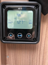
image0.jpeg

I read as the hab battery is currently 12.7 v (more or less full?), Solar is starting to kick in.
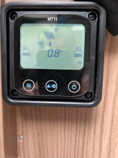
image1.jpeg
Panels are generating 0.8amp…
image2.jpeg

…and 2.7 amps are being put into the hab battery.
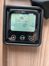
image3.jpeg

Then after a bit of more light, there’s enough to charge both Hab and starter batteries, with 1.0amp going to the starter…

image4.jpeg

And 7.7amp going to the hab.

The hab battery is now showing 13.5v. Is that the voltage that is being charged at or the actual voltage of the battery currently?
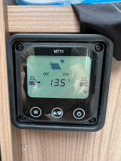
image5.jpeg


When the battery is ‘full’, whatever that is, does the amp to the hab batter go down from its say 7.7amp to zero or just a very low reading?

I expect I’m being very simplistic about it here, I just wanted to know what to look out for on the monitor say when it’s sunny and the battery is fully charged! Do the little chevron type arrows towards the batteries go out?

I have the mppt unit set as Flooded 12v (as directed by the battery supplier) and that apparently has parameters of:

Over Voltage Disconnect Voltage 16.0V
Charging Limit Voltage 15.0V
Over Voltage Reconnect Voltage 15.0v
Equalize Charging Voltage 14.8v
Boost Charging Voltage 14.6v
Float Charging Voltage 13.8v
Boost Reconnect Charging Voltage 13.2v
Low Voltage Reconnect Voltage 12.6v
Under Voltage Warning Reconnect Voltage 12.2v
Under Volt. Warning Volt. 12.0v
Low Volt. Disconnect Volt. 11.1v
Discharging Limit Voltage 10.6
Equalize Duration (min.) 120
Boost Duration (min.) 120
Any help or guidance will be gratefully received.
Cheers,
Peter

Sent from my iPad
 
Hi, Peter,
the battery capacity readings on Epever solar chargers are very approximate since they are based on battery voltage. Battery volts will increase when under charge, fall to resting voltage with no charge or load current, and will also vary with load current.
The voltage reading on the display is the volts at the battery terminals, so will vary as indicated above. Only after a rest period will the voltage be near 'true' battery volts. With your EFB batteries, (L36 Yuasa?) fully charged, resting, should be in excess of 12.70 volts. Note a low cost meter and Epever readings may have calibration errors.
The batteries will be fully charged when the voltage reaches boost volts, 14.6, and this voltage is steady at this value for 120 minutes boost duration, after this period the charge volts drop to float level. During the boost duration period the current Into the batteries will fall to a low value, less than 1 amp per 100Ah of battery. ( note the Epever can only see current put into the system, thus it reports battery current plus any load current). Due to variable solar, especially at the moment in Devon UK, ( I am in South Devon), its very probable the charge current will vary and often be low due to poor solar conditions.
A useful addition to any RV battery system is a battery monitor to indicate state of charge. This can be considered as a kind of battery 'fuel gauge'.
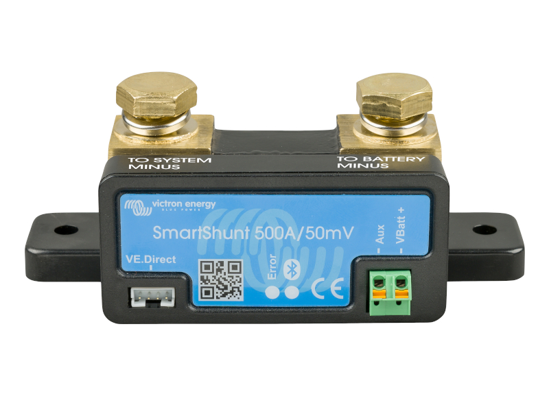
The Victron Smart Shunt is recomendecd.

Summary.
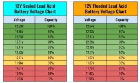
Epever display of battery capacity , is very inacurate. Resting voltage of battery compared to chart below is a better guide.
Whenever there are good solar conditions some current, perhaps very small, will flow Into the battery even when fully charged.

Depending on battery chemistry the resting voltages will differ slightly, most vehicle derived have calicum added to the lead so the resting voltage is higher shown as for the sealed battery
lead acid SOC.jpg
Mike
 
Last edited:
Hi Mike,
Thanks so much for that explanation! That really helps. I will look into the Victron smart shunt…I think I need to be getting accurate information to start with…

Something else you may be able to give advice / opinion on if I may…

The Motorhome currently has the 245 w solar panel on, primarily because I wanted to install a 12v compressor fridge (the old dometic 3 way was pretty poor for very cold beer and ice!). I now have a Danfoss based Vitifrigio compressor C115i fridge (45w) which cools down very nicely, but I’m aware for wild camping stints in the UK, 245w solar in our conditions may be a little limiting…I was only getting about 150 w ish during a sunny spell yesterday lunchtime. The fridge I’m told is efficient but I’d rather have a bit more solar going into the batteries rather than be fretting that there wasn’t enough.

So i have a couple of extra slim 100w panels that I haven’t yet installed. Since i can’t really pair them with the panny panel along with the current EPever controller, I was wanting to add them as a parallel pair and connect them to the leisure batteries via their own Mppt solar controller, one I used before I had the panny installed, a votronic duo 250 Which previously behaved very well. The extra potential 200 w could give me a bit more headroom during less favourable days.

I sought advice else where previously as to if this is ok practice, so effectively I’d have two solar controllers putting power into the same battery bank and was told it was fine to do this. This was from someone who apparently had a similar set up.

I’d be very interested to hear your view on this? Just wanted to be aware of any potential issues or conflicts that may occur.

cheers,
Peter
 
I’d have two solar controllers putting power into the same battery bank and was told it was fine to do this.
It is totally fine to have multiple chargers for your battery bank. The only thing to watch out for is charging too fast (too many amps) if both systems were powered on a sunny day (and your alternator was also charging). Does your battery list a max charging amps?
 
It is totally fine to have multiple chargers for your battery bank. The only thing to watch out for is charging too fast (too many amps) if both systems were powered on a sunny day (and your alternator was also charging). Does your battery list a max charging amps?
Good point…I’ll look up Yuasa and see… thanks for the info!
 
The battery supplier has told me the L36 EFB batteries can take 40 amp each or 80 as a bank of 2.

So rough calculation, at max production and a bit extra of 17amp produced by the EPever mppt from the pan HIT panel and around 14 amp for the two 100w via the votronic, add about 15% leeway and it’s total of about 36 amps under full production. So that leaves 44 amps for either the van during running or charging on EHU If either the two coincided With full blasting solar.

The EHU charger gives a max of about 20 amps to the batteries and to be honest I’m not sure what the alternator pumps out and whether that goes in via the control from the power unit…there’s no AtoB or BtoB fitted and I under stand that British motorhomes are incredibly under powered / limited by poor wiring choices so I’m sure that it won’t be an issue! I may just confirm that though…All the power lines to the batteries have fuses so I think I’m all right…
 
Your battery supplier wants to sell more batteries. Charging a 100 Ah lead acid, non AGM, sealed battery at 40 amps will not end well. You want something less than 20 amps per battery for long life. 10 to15 amps per battery would be the usual recomended charge current. Lead acid batteries tend to self limit the charging current unless you set stupid high charge voltages so its difficult to 'force feed' the batteries. For your batteries a charge voltage, absorbtion voltage, ( boost voltage in Epever speak) of 14.4 volts, float at 13.8 volts , equilisation volts, set same as boost volts.
In the UK for horizontal mounted panels expect around 70% of rated power , May to September, very little in mid winter.
I doubt you will exceed 40 amps into the batteries, 445 watts of panels at a charging voltage of 13.5 volts gives 33 amps for ideal solar conditions. Realistically with horizontal panels and power loss due to increase in panel temperature, expect something in the 25 amps range.
The alternator charging, if your motorhome is typical production with a split charge/ VSR, it will not impact very much on charge current when you have solar charging putting power Into the batteries.
With AC charging a similar situation exists as the usual charge voltages are modest.

Note, as I pointed out, lead acid batteries self regulate to some extent and this effect increases as the batteries near full charge. From around 70% state of charge the battery accepts less and less current, regardless of the available charger power. Thus it takes longer to fully charge than expected. A half discharged lead acid battery will take at least 5 hours to fully charge
 
Thanks Mike…again, really useful and has put my mind at rest, especially about the partial self regulation aspect. And using in Spain, probably the potentially brightest country we’ll be going to for a little while, the added heat will reduce efficiency so amp availability as you say isn’t going to pose much of a problem!

it’s a bit of a minefield for total amateurs like myself. I suppose my initial thoughts were that chargers / solar panels are pumping charge / amps into the batteries at particular voltages where as as I now understand it, a battery will pull the charge in depending to an extent on the limit that is available at that time from what ever source?

just been into the van and it’s on mains charge via the Sargent px300 that’s integral with the Motorhom overnight. Nice and sunny and the horrible little power display (MT-11) is showing just over 50v coming from the panel but only a v small amp of 0.1amp and wattage of 6. I now take this as the battery is full (14.0v showing on the display, pinch of salt) so it doesn’t need to take any heavy amps from the Mppt hence the low reading on the amp arrow from the battery (0.8) and also the low amp arrow coming from the solar panel And the low wattage showing. The max volts for the battery are showing as 15.8 v..is this due to the relatively low temp at the batteries (temp compensation sensor is attached, temp current at 10 deg C)?

I do find it a bit misleading though, I suppose in my own mind, it’d be nice to see what the solar panel is outputting volt wise, (which I can see) and what that equates to as power available to the mppt in terms of watts and amps, rather that what appears to be happening, what the mppt is actually drawing from the panel to supply a reduced trickle to the battery. Makes me doubt the panel is working!

pension comes in in just under a week so I’ll treat myself and the van to a Victron smart shunt as you suggested. It’ll give me an excuse to tidy up cabling and check connectors etc.
 
With lead acid you can consider the batteries full when the current into the batteries falls below 1 amp per 100 Ah whilst the chargers are at absorbtion volts, boost volts, of 14.4 volts.
If at any time you want to see the actual panel output apply a heavy DC load on the batteries or deliberately discharge the batteries to a low, 50% state in advance
It's around 10 degC minimum in my part of Devon so I cannot see a charge voltage of 15.8 being valid.
I can't find a temperature coeficient for EFB batteries, I would expect something like 3.4 mV/ deg C/ cell, this corresponds to 0.3 volts added to the absorbtion volts, boost volts, setting
 
Back
Top