diy solar

diy solar

Multiple Battery Banks across Several Paralleled Inverters???

WattAboutThat

New Member
Joined
Dec 15, 2021
Messages
123
I am working on designing a new system using the new eg4 6000 split phase inverters along with the eg4 rack battery system.

Here are a few of my questions, if anyone could please advise your recommendations:

1) It is my understanding that you can only have a max of 16 batteries on a single battery bus going to the inverters which are also in parallel.

If I want to have longer term storage than 16 rack batteries, lets say 32 or more, would it be advisable to have more than one group of 16, so for example battery stack A has 16 units, and battery stack B has 16 units, such that I would only connect two of the paralleled inverters to Stack A, and say two more inverters to Stack B, assuming a 4 inverter system, (maybe could even expand this concept to 6 or 8 inverters, with each two or three inverters on their own battery Stack)?

If this were done, and if one battery stack goes low on power, such that those inverters are not able to produce as much AC, but the other stacks still have power and those inverters are producing AC, would this create an issue, if all the inverters are paralleling their AC out, to the breaker panel, resulting in the non or low producing inverters, will be at low or no amperage, could those inverters at low or no amperage be damaged by the output from the producing inverters?

Please advise your opinions on this.


2) A second almost completely different topic,
does anyone have a calculation or formula,
which I can use to determine
the minimum, and maximum number of
solar panels, which I can put on each
mppt input of the 6000 split phase, and
how many panels should be in series
versus parallel,
given the known wattage of any selected panels?

Is there a web site, where a person like myself, could enter the wattage of the desired solar panels, and have it calculate max and min total (in series and in parallel) panels that can be connected to the mppt input on the 6000 split phase?

thx
I am planning something similar. I am trying to figure out wiring for two racks of 6 each Signature Solar 100ah 5.12kw Lifepower batteries and 4 EG4 6500w inverters split phase with 32 455w solar panels. My current plan is essentially two independent systems powering one 200amp electrical panel. Each of the two independent systems would be connected to 16 solar panels feeding 2 EG4 inverters, and charging 1 six pack rack of batteries. So the solar cables and battery cables are independent of each system, however, the AC wiring would come together by making one systems hot wires of the 2 inverters L1 and the other L2 feeding to the AC panel. Then the 4 ground wires and 4 neutral wires of all 4 inverters would all feed to the busbars of the AC panel. As you noted above, I just don't know if there are any risks.


In regards to your second question, inverters state they have a max VOC, which on the EG4 6500 is 500 VOC. My solar panels output 50 VOC each + it's a good idea to leave a 20% buffer, so I can connect 8 of my panels safely for a total of 400 VOC.
Following to see replies. thx
 
I posted this in the other thread about parallel inverters with separate battery banks, I don't know if it's specific to victron or not:

"Every DC connection (on every Multi/Quattro and on every battery) has to be connected together to a single DC bus. Do not build systems with separated batteries on multiple (separated) DC bus structures connected to subsets of the Multi/Quattro units in the cluster. This will not work."
 
Well this is what I'm wondering... If you have two inverters, and they are not in parallel on the DC side, but are on the AC side, then it seems like you could have two separate battery banks, one being charged and providing power to each inverter on the DC side, then both inverters feeding an electrical panel on the AC side. I have attached my wiring/hardware plan. Would welcome feedback. I want to do this right.
 

Attachments

  • McGuffin.Home.Power.Setup.vs2.pdf
    324.6 KB · Views: 35
Last edited:
I want to do this right.
Nice color drawing BTW. I would make 2 minor changes.
1) Tie the battery racks together using the Battery combiner bus bars (the 4 stud ones with the red and black boxes around them) so they are always at the same State of Charge as per the Charleswgibbs post above.
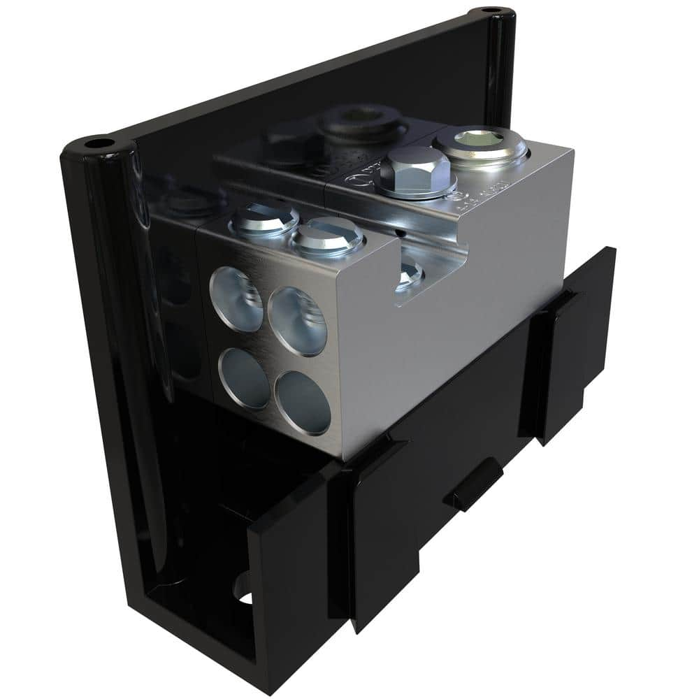
2) Use something like a mechanical lug distribution block for the High Voltage for L1 & L2 instead of the 4 stud bus bars. Mount the distribution blocks in a suitable metalic J box. The items show below are for reference only, please verify specifications for your particular use case.


Ok. Based on comments from Bentley and others, I found a 1200amp bus bar on ebay I could use to merge my two battery banks together. So I also changed and removed several of my bus bars. Now all the ground and neutral wires will just go directly to the Electrical panels bus bars. I will probably keep my two bus bars I'm using to merge together for a single L1 and L2 lines that will run to the electrical panel, but I think what I can do is mounts those 250amp bus bars in a box. See updated layout.
 

Attachments

  • McGuffin.Home.Power.Setup.vs3.pdf
    369 KB · Views: 20
I am planning something similar. I am trying to figure out wiring for two racks of 6 each Signature Solar 100ah 5.12kw Lifepower batteries and 4 EG4 6500w inverters split phase with 32 455w solar panels. My current plan is essentially two independent systems powering one 200amp electrical panel. Each of the two independent systems would be connected to 16 solar panels feeding 2 EG4 inverters, and charging 1 six pack rack of batteries. So the solar cables and battery cables are independent of each system, however, the AC wiring would come together by making one systems hot wires of the 2 inverters L1 and the other L2 feeding to the AC panel. Then the 4 ground wires and 4 neutral wires of all 4 inverters would all feed to the busbars of the AC panel. As you noted above, I just don't know if there are any risks.


In regards to your second question, inverters state they have a max VOC, which on the EG4 6500 is 500 VOC. My solar panels output 50 VOC each + it's a good idea to leave a 20% buffer, so I can connect 8 of my panels safely for a total of 400 VOC.
You need to look at the max amperage of the 455's. If your inverter can support 20a inputs from the solar, you can also parallel another leg of 8x455 panels in series together. Basically you wire up the first 8 panels in series and use a parallel cable to connect another set of 8 panels in series. The voltage stays within the tolerance of max VOC but the current will double, so 10ga wire is recommended. On my solar setup, my sunny boy has a max voltage of 600v and with panels @ 37.1v VOC, I can hook a total of 30 panels to the system, two sets of 15 panels in serial (30v max vpwr) for a total of 30 net panels on a single 10awg solar wire. My panels are older 235's and each leg can now support 7500 watts of pv - around 6000 watts net at 80% or so. I only have a 10% margin from the 600v on the VOC - so some areas might want to run 14 panels in series vs. 15 in my case.
 
Well this is what I'm wondering... If you have two inverters, and they are not in parallel on the DC side, but are on the AC side, then it seems like you could have two separate battery banks, one being charged and providing power to each inverter on the DC side, then both inverters feeding an electrical panel on the AC side. I have attached my wiring/hardware plan. Would welcome feedback. I want to do this right.
I like your design as shown in your pdf a lot!!!
My only concern (and I am not an expert),
is how do we make the AC output of the two systems L1, L2, N remain in phase with the other?

If the inverter paralleling cable can be used between the two separate system to keep them in phase that would be great.

So the question, to anyone out there with experience, can two or more completely isolated systems (on the DC side), be placed in parallel (using the cat5 and/or serial cables), to keep all system AC output in phase, so all outputs can be combined on the AC side, then used to feed a critical loads panel?

I like this design, because it will essentially remove a single point of failure. If one system fails, the other remaining systems can still feed the AC combiner panel. You might need to change a paralleled slave inverter to become the master, but only in the event the original master was the inverter that failed. Again I am not an expert, and I am seek feedback from experienced designers. thx
 
The biggest challenge I was facing was how to connect the two 600ah batter banks together. Signaturesolar.com recommended a 1200amp bus bar. Those are hard to find, but I lucked out and found a few on eBay and bought them, then updated my design. See attached. No longer going with two separate battery banks.
 

Attachments

  • McGuffin.Home.Power.Setup.vs3.pdf
    369 KB · Views: 19
Nice color drawing BTW. I would make 2 minor changes.
1) Tie the battery racks together using the Battery combiner bus bars (the 4 stud ones with the red and black boxes around them) so they are always at the same State of Charge as per the Charleswgibbs post above.
2) Use something like a mechanical lug distribution block for the High Voltage for L1 & L2 instead of the 4 stud bus bars. Mount the distribution blocks in a suitable metalic J box. The items show below are for reference only, please verify specifications for your particular use case.


This eliminates the goal of having isolated systems. And I am trying to keep as much isolation as possible until it goes to the AC combiner breaker panel to then be connected to a critical loads panel. So my goal is to gave the battery banks isolated with their repective inverters and solar panels.
thx for any additional feedback
 
The biggest challenge I was facing was how to connect the two 600ah batter banks together. Signaturesolar.com recommended a 1200amp bus bar. Those are hard to find, but I lucked out and found a few on eBay and bought them, then updated my design. See attached. No longer going with two separate battery banks.
I am still seeking a design with separate battery banks. thx
 
So as a follow up question: Does anyone know how to control the AC output from two or more isolated systems so that they are:
1) in Phase on L1, L2, N, G
2) can be combined in an AC breaker box, using separate breakers for each input from each inverter, then one output from that AC combiner box, that will feed the main input of the critial loads breaker box.

This will permit adding or removing any individual system from the feed for critical loads, while maintaining power to critical loads from remaining systems, as needed or in case of failure, by turning off breaker in AC combiner box for repair, or adding a new system for added power.

So each system is isolated up and until it connects to the AC combiner panel.

Then as need more power, build a new system and connect to AC combiner panel.

The only issue is making sure AC lines are in phase - so need dome method of communications between inverters, or some kind of CT coil to monitor phase of a primary master. If a CT coil can be used to drive phase of each system.

Seeking feedback. thx
Hello
I realize this thread is a few years old but it seems to have ended abruptly. How did it turn out for you? How to you assure in phase AC?

We are seeking to do a similar system with Schneider or Victron but both are advising against it.
 
Back
Top