diy solar

diy solar

Multiple battery

ArthurEld

Solar Wizard
Joined
Aug 3, 2020
Messages
2,298
Location
Palm Harbor, Florida
I plan to use multiple 48v 280a battery packs. My hybrid inverter / charge controller manual says to connect the batteries parallel.
How do I keep the other batteries going if one BMS needs to disconnect?
 
If you are connecting 48V batteries in parallel and the BMS in one battery disconnects for some reason the others will continue to provide (or accept) current. You don't have to do anything to keep the other batteries going.

There is something to be aware of. If your load is drawing more current than the remaining batteries are happy to provide their BMSes will trip too, perhaps all at once, or in rapid succession. Charging has issues too. If your charger is providing near full rated charge current to each battery and one trips off the others will take their share of that now spare capacity. That could result in higher than acceptable charging rates, and again perhaps more BMSes tripping.

How many batteries are we talking about here? It may be advisable to have fuses or breakers between each battery and the common + wire. What is your expected peak amp draw from the battery bank?
 
If the Batteries are connected parallel, and one BMS disconnects, doesn't that stop the flow to the other batteries?
I will be using 4 batteries each with it's own BMS. I haven't gotten to the breakers and fuses and wires yet.
I assume my manual tells me to connect the batteries in parallel is to help them stay balanced.
If I connected to busbars instead of parallel it would be simpler. And that is what I will do if I find out it is ok.
The other thing I want to avoid is having all of my batteries disconnect from the charge controller.
 
Not in parallel. If they were in series that would be the case. In parallel each BMS can only control current in / out of its own battery. All the BMSes will still react to a common problem at the same time though. If your charger goes over voltage all the batteries will trip.

When you hook them up in parallel you need to take care with the wiring to ensure each battery carries the same amount of load. Check the forum FAQ for wiring batteries in parallel. The other option is to use equal length wires from each battery to a central bus bar.
 
Thanks gnubie.
This is how the manual shows multiple batteries. Each pack is made up of four 12v cells.
So there are four 48v battery packs.
Doesn't the BMS break the flow through the main power line when something goes wrong?
multi battery.png
 
It depends on what you call a BMS and where it is. I assumed you had separate 48V lifepo4 batteries each with their own BMS since this is typically what people here are doing with separate lifepo4 batteries.

Are you doing this or do you have something else in mind?

From that diagram, if you look at either the red + wire or the black - wire they go to each battery directly rather than looping through a battery to get to another. If the BMS in one battery trips the others are still connected to the common wiring.
 
Mine are lifepo4 EVE 280ah. Each 48v battery is sixteen 3.2v cells.
I am ignorant about this and maybe I need to find a BMS manual to read.
I thought the BMS is connected between the common line and the common line is the only line it can disconnect.
 
Gnubie answered questions spot on.
A good reference doc you should look over, starting at Page 17. VICTRON Wiring-Unlimited-EN.pdf

Standard Good Practice simplified.
48 Volt 16S Pack with 16S BMS to manage each cell and it's entire pack as an independant entity.
All Packs set in Parallel with equal length identical wiring to BusBar Block (the most efficient connection method)
Each pack with it's own Fuse. (MRBF Fuses work a treat for this)
! Each pack must be capable of handling the FULL Charge/Discharge rates the equipment can take/push. With multiple packs in a bank, each pack must be able to handle the "full deal" in the event the other packs cutoff for any reason, otherwise failures will occur.
Properly Paralleled packs can share Load & Charge equally and if all packs are matched up properly, they shoudl all work in tandem, yet if one or more packs get out of sync they can continue to function untill fully recharged collectively.

Caveats:
- Ensuring that the BMS' on each pack are set with identical cutoff points for Hi/Low Volt cutoff & Temp Cutoffs. If not set properly, teh packs will not interact as well as they should.
- The entire system needs to be Voltage Calibrated. This is to ensure that when the SCC reads 50.0V at "it's terminals" that the voltage at the Busbar is exactly the same and the same applied to the Inverter/Charger as well. THESE CANNOT BE OFF ! THIS IS CRITICAL with Lithium Battery Systems where 0.5V can make a real difference. See link in my signature related to Calibrating.

- Multiple BMS' will act independently BUT this creates a Problem too with "some" equipment. With some gear, they have the ability to communicate with a BMS and interact with it, to do such things as shutdown or idle an Inverter or even interact with the SCC to control charging. MOST BMS' cannot work in a "pool" of BMS's that can interact with a "single" device. This would reqquire an "Intermediary or Monkey in the Middle" between the battery packs in the bank and the devices. The BMS Tech exists for this, it's called Distributed BMS' but you had better be sitting down and have a Tylenol bottle on hand before looking at the costs. Maybe even a quadruple shot of Jack Daniel's.

- BMS' in General: There are several types of BMS', some will do series, some will do parallel and some do both. There are Relay/Contactor models which handle higher amperages and there are mosFET based ones without Relays/Contactors (typically cap around 200A Discharge / 100A charge). The BMS choice depends on the Inverter Draw Capacity & the Solar Charge Capacity. If the invverter will pull 5000W / 105A from the batteries & the SCC can push 100A Charge, you will want to ensure teh BMS' on ALL packs can take 100A Charge and comfortably discharge 105A (just random numbers) with FET based BMS' you woudl want at least 25% overhead space so as to not tax the BMS and push it to the edge of it's specs. The CATCH or GOTCHA, typically FET Based BMS' allow for 50% charge rate compared to their discharge rate. So a 200A Fet BMS would allow for 200A Discharge & 100A charge rate. This is quite normal.

280AH cell Note. They are Commmodity Grade-A Cells, which means they qualify as Grade-A and fit teh Factory specs and tested to comply with that spec, (it's a general spec) but these cells are NOT factory Matched & Batched, they are only basically simple Voltage & IR matched at "one voltage - the storage voltage".
These cells can discharge at 1C rate or 280A max.
These cells can charge up to 1C rate BUT the recomendation is to not exceed 0.5C rate or 140A for maximized life, performance & thermal control. The higher the rate the more heat the cells will generate due to the chemicial interaction. These commodity cells can easily see 1mv per Amp Hour differential between the cells and this will be more pronounced at the low & hi SOC states. Passive Balancing on these cells is almost pointless UNLESS they have been perfectly Matched & Top & Bottom Balanced. (propely Matched & Batched cells cost much more it is a long process of testing, evaluation and batching)

Some Refrence info for you. Orion BMS company has excellent docs, and it is an excellent BMS company, so...
BU-803a: Cell Matching and Balancing – Battery University
Pre-Balancing Cells | Orion Li-Ion Battery Management System
High resistance cell | Orion Li-Ion Battery Management System
 
Thanks Steve and gnubie. I'm dreaming up problems that don't exist.
I do plan to try and match my cells the best I can.
My main reason for using batteries is UPS and so I can use my solar panels when the grid is down. I also want to use critical loads when the grid is down and the sun isn't shining.
 
ArthurEld, the way I "parallel" connected my two batteries is that I ran 2/0 cables from each battery to the necessary common connection points. In the picture below, you can see that each battery's negative goes to the shunt and each battery's positive goes to the fuse. In my case, I wanted each battery to be independent, with no connection between the batteries.

20200903_190817-jpg.21889


Since you have four batteries to connect I would use a bus bar between the batteries and the common connection points. I say this because there aren't enough threads on the shunt or fuse block to handle four stacked lugs.
 
Last edited:
Thanks HRTKD. Did you forget to add a picture? I think I understand what you mean. You are saying each battery and BMS branch off the common line. And that is still considered parallel. I knew it had to be something like that.
Now I need to make a drawing that shows how I plan to connect everything.
 
Picture added to my prior post.
It looks like you did the joinery on the b- side of the bmss differently between the batteries.
Have you tested to see how well the batteries share the load?
 
It looks like you did the joinery on the b- side of the bmss differently between the batteries.
Have you tested to see how well the batteries share the load?

Yes, I did change my approach. There were a few reasons.
1. Good grief, connecting three separate leads sure is sloppy.
2. Loss due to stacking three lugs? Maybe.
3. Need longer bolts to securely fasten three lugs instead of one.
4. I was running out of 8 awg lugs.

The only "check" I've done is to look at the voltage readings - after using the inverter - as provided by each BMS. They're spot on. Not the greatest measure, perhaps. But's what I had available at the time. Given that my SOC - as reported by the Victron BMV-712 - never went below 93%, I haven't put any stress on these batteries yet.
If those are overkill bms I think they will show current from the pov of the bms.
 
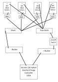
Ok guys, I made a picture. Please let me know if anything looks wrong.
One thing I am wondering is if I should use 4 fuses and 4 shunts?
My Inverter/Controller is 185A max. I don't think I should go higher than 140A. And I probably will never go that high.
I need to figure out my fuse amps, shunt amps and wire sizes. I will start digging for that info.
If a BMS shuts down one battery I want the other 3 to keep going.
Battery connections pic.png
 
My Inverter/Controller is 185A max.

12000 ac watts * 1.15 inverter efficiency / 48 = 287.5 dc amps
287.5 / 3 = ~96 amps per battery.
You should be able to run full tilt with a single pack off-line.
Each pack should be individually fused to ~125 amps.
For bonus points put a shunt on each pack so that you can tell if they are pulling evenly.
Make sure that you are not charging to aggressively for the 3 packs as well.
 
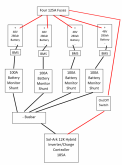
I updated my picture and I tried to look up the size cable I will need.
I think 2/0 AWG from the inverter to the power switch, fuseblock to power switch and inverter to negative busbar. And 3 AWG for the rest.
I think that is thicker than the minimum recommended. My cables will be less than 6 feet.
The battery monitor shunts were either 100A or 350A. I don't know if 350A would be better.
Battery connections pic.png
 
So far, I'm liking my Victron BMV-712 for battery monitoring. I would not want to have four of them. There is a new-ish product from Victron that is just the shunt and it has some smarts in it. Enough that you could go with that and skip the wall readout that is used by the BMV-712.

However, having to aggregate the data from four shunts would not be what I consider an elegant solution. If possible, I would stick with one shunt, even though I understand the suggestion for monitoring each battery. If one of Victron's other monitoring solutions can do the aggregation, then that would be a good way to go.
 
Back
Top