diy solar

diy solar

Multiple BMS configuration

RoySalisbury

New Member
Joined
Apr 24, 2022
Messages
136
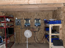
I have now completed my 5th (out of 8) pack for my DIY system (16x280ah in each bank). I switched away form JDB over to JK BMS for the active balance capabilities and this has helped stabilize the voltage differences between cells and between the 5 BMS's.

But I am wondering, of the folks that have larger banks (48 or more cells), do you just manage multiple BMS's individually, or have you moved on from "single" pack BMS's to something that can communicate between packs? For example, the JK or JBD BMS are basically "stand alone" BMS's that monitor a single 4/8/16 cell pack. But the All-In-One (not DIY) systems like EG4, are designed to be "daisy chained" together so they can act as one large bank. This allows them to communicate with the inverters and help manage the charging better.

I have noticed that a "one size fits all" charging profile just does not seem to be the right choice when you have multiple packs and they have slightly different charge cycles. I have 2 EG6500EX inverters and when dealing with the battery "source" all it knows is basically the voltage because it has no communication to the BMS. So the only charging "profile" it has is voltage (bulk/float) and max current. And its SOC is rarely if ever correct (because it just uses the voltage).

It also cant adjust the charge current based on SOC when getting closer to 100%. This is actually both a BMS and inverter thing, but the JK or JBD BMS do not have any type of current limit other than "max" current, so I need to adjust the inverters max charge current the closer it gets to 100%. if not you can get spikes of "over voltage" in some cells that causes the BMS to turn on/off, while other cells don't get fully charged (this is where the active balancer helps).

Anyway, what are some recommendations/ideas that folks have? In the end I will have 8 packs 16x280ah (for a total of about 114 kwh), and would like to start getting some better management in place.

Roy
 
So the only charging "profile" it has is voltage (bulk/float) and max current. And its SOC is rarely if ever correct (because it just uses the voltage).
What is your voltage based charge profile and what kind of incorrect Soc readings/events are you seeing?

One of the bigger problems with batteries in a bank becoming imbalanced is improper wiring configurations. Can you describe your battery bank wiring and post a pic? Wiring 8 batteries offers wiring opportunities from good to bad to horrific.
 
But I am wondering, of the folks that have larger banks (48 or more cells), do you just manage multiple BMS's individually, or have you moved on from "single" pack BMS's to something that can communicate between packs? For example, the JK or JBD BMS are basically "stand alone" BMS's that monitor a single 4/8/16 cell pack. But the All-In-One (not DIY) systems like EG4, are designed to be "daisy chained" together so they can act as one large bank. This allows them to communicate with the inverters and help manage the charging better.
That's not completely true. Communicating data is one thing. Actually having hardware that can modulate Chg/Discharge currents built in to each battery is another thing altogether and none of them do. Here is good YT video about proper wiring for multiple batteries in parallel.
I have noticed that a "one size fits all" charging profile just does not seem to be the right choice when you have multiple packs and they have slightly different charge cycles.
While individual batteries may indeed have slightly different charge profiles any minor differences are going to be automatically corrected especially at the top and bottom of the charge curves. As one battery begins to experience a deviation in voltage compared to the others, current will naturally flow more to the lowest battery or less to the highest battery. Eventually they all will reach full charge if the absorption voltage and charging duration are chosen properly.
I have 2 EG6500EX inverters and when dealing with the battery "source" all it knows is basically the voltage because it has no communication to the BMS. So the only charging "profile" it has is voltage (bulk/float) and max current. And its SOC is rarely if ever correct (because it just uses the voltage).
Yes, that seems to be an industry wide problem. Most BMS do not have good Coulomb counters. However, there should be NO need to adjust charging current. As the battery reaches full charge it will naturally "push back" and current will fall off. This is how chargers know when to exit absorption and enter float (if float is used). If some of the BMS are disconnecting its because the cells are out of balance and/or the charge current is too high and there is not enough absorption time to allow balancing. Reduce the voltage to a value that does not cause BMS disconnect and let the batteries absorb for a few hours then increase by 0.1V until you reach the desired voltage.

Anyway, what are some recommendations/ideas that folks have? In the end I will have 8 packs 16x280ah (for a total of about 114 kwh), and would like to start getting some better management in place.
If you have that may DIY packs I would recommend you invest in this Stand Alone 10A Bluetooth JK BMS brand active balancer. It comes with aligator clips so is fairly easy to use and move from battery to battery. Remember to turn off the BMS balancer when using an external stand alone device. https://www.jkbms.com/product/jk-b10a24s/
 
What is your voltage based charge profile and what kind of incorrect Soc readings/events are you seeing?

One of the bigger problems with batteries in a bank becoming imbalanced is improper wiring configurations. Can you describe your battery bank wiring and post a pic? Wiring 8 batteries offers wiring opportunities from good to bad to horrific.

I will admit that the cable lengths are not exactly the same form each bank back to the inverter. You can only get so close. I don't have any pics at the moment, but can explain the layout a bit. There are currently 3 shelves in the rack that each hold 2 packs of 16 cells. Each shelf is wired to a bus bar with about 18" of 4 gauge wire on the + side, and about 6 " on the negative. Each shelf in the rack then has its bus bars connected using 2/0 gauge cable (about 18" between each shelf). Then the center shelf bus bar has a 2/0 cable back to the inverter.

At most there is about 6' from the farthest battery to the inverter (the shortest is about 4') .. Due to cable size, resistance and voltage drop are kept to an absolute minimum. Each BMS is calibrated to the voltage measured by a calibrated voltmeter against is fully charged pack (3.625 per cell).

As for SOC readings, since the inverter knows nothing about the SIZE of the bank the only way it can determine the SOC is based on ranges of voltage. For example, right now my average SOC for the bank is 82.8% (based on BMS readings). But the inverter says its 91% because its looking at voltage (which is higher when charging then when under load). It has no indication of amp/h in or out (only the BMS or a separate shunt will know that).

My charge profile on the inverter is as follows:

Bulk: 58
Float: 56.4

Each BMS is set to
Cell Over Voltage: 3.625
Recovery Voltage: 3.85
Balance Start: 3.425
 
hold 2 packs of 16 cells.
Is this 2x 48V batteries?
Bulk: 58
Float: 56.4
58V / 16 = 3.625Vpv
Why are you charging this high? Your cells are essentially full at 3.45Vpc.
And with your BMS cell over volt set to the same voltage, you probably have the BMS cutout every charge cycle.
This is very unnecessarily hard on everything in your system.

56.4V / 16 = 3.525V
This too is necessarily too high. I like to set float to just below where MY cells setting an hour after a full charge. This prevents micro-cycling (charge, settle charge, settle...). You should set your float just below where YOUR cells settle.

What does your charging look like each cycle? How many amps are you charging at?
Charges fast and furious and done by noon?
 
My charge profile on the inverter is as follows:

Bulk: 58
Float: 56.4

Each BMS is set to
Cell Over Voltage: 3.625
Recovery Voltage: 3.85
Balance Start: 3.425
Thank you for posting the values: Here is the problem.

Bulk set at 58V which corresponds to 3.625V per cell which absolutely guarantees that the BMS HV cut out will get triggered EVERY time near the end of a recharge cycle. Reduce it to 56.0V (56.8V max)

LFP batteries do not need float and may even shorten life span. I would recommend turning float off if possible. At the very least reduce it to 53.6 to 54.0V. In the short term you may use a float at 55.0V to give the BMS time to balance all the cells, then reduce it per above.

Recovery Voltage?? If this is the setting where the BMS reconnects after a HV disconnect it should be set lower than the HV cut out, for example 3.575V.

Balance can start at 3.40 to 3.425V
 
That's not completely true. Communicating data is one thing. Actually having hardware that can modulate Chg/Discharge currents built in to each battery is another thing altogether and none of them do. Here is good YT video about proper wiring for multiple batteries in parallel.

That video is again dealing with BMS systems that can communicate to each other (one BMS to another with a single CAN connection to the inverter).

While individual batteries may indeed have slightly different charge profiles any minor differences are going to be automatically corrected especially at the top and bottom of the charge curves. As one battery begins to experience a deviation in voltage compared to the others, current will naturally flow more to the lowest battery or less to the highest battery. Eventually they all will reach full charge if the absorption voltage and charging duration are chosen properly.

Up to a point, yes. But without some type of active balancing system even normal bulk/absorb/float cycles are not enough to keep them in sync. If I have 15 cells at 3.6v and one at 3.4v, that lower cell is never going to get up to 3.6v on its own. The overall voltage of the pack will not let enough current flow without over voltage shutdowns on the BMS, and the resting voltage will get low enough that they all start reading the same voltage. (Its why SOC readings cant be used based on voltage .. its not linear).

If some of the BMS are disconnecting its because the cells are out of balance and/or the charge current is too high and there is not enough absorption time to allow balancing. Reduce the voltage to a value that does not cause BMS disconnect and let the batteries absorb for a few hours then increase by 0.1V until you reach the desired voltage.

This is actually what I have done a few times manually. Once teh inverter gets to the point that it "think's" that the bank is full (based on voltage cutoff), then I will go in and raise the float voltage a tiny bit at a time so that it does not overload the current. Even with "over voltage" protected on the cells set at 3.25v, I have seen a cell it spike up to 3.75 with a large inrush of current when other cells can still handle it. It a balancing act.

This is why the recommendations that I have read, and some systems employ, is that there is a current "step" that should be used during charging LiFePO4 batteries. For "example": up to 90% - 50amp, 91-95% - 30amp, 95-97%: 20amp, 98-99% - 5amp, 100%, 1 amp ... (These numbers depend on bank size of course. I believe I have seen this in Victrons documentation, but cant remember exactly where. But it requires the BMS devices to all be communicating together).
If you have that may DIY packs I would recommend you invest in this Stand Alone 10A Bluetooth JK BMS brand active balancer. It comes with aligator clips so is fairly easy to use and move from battery to battery. Remember to turn off the BMS balancer when using an external stand alone device. https://www.jkbms.com/product/jk-b10a24s/

This is a good suggestion. I'll have to look into this.
 
Is this 2x 48V batteries?

Yes. Each pack is 48v (16 - 3.2v cells). And each shelf holds to packs. I actually found an old image (pre-cable management when I first built the shelf).

58V / 16 = 3.625Vpv
Why are you charging this high? Your cells are essentially full at 3.45Vpc.
And with your BMS cell over volt set to the same voltage, you probably have the BMS cutout every charge cycle.
This is very unnecessarily hard on everything in your system.

56.4V / 16 = 3.525V
This too is necessarily too high. I like to set float to just below where MY cells setting an hour after a full charge. This prevents micro-cycling (charge, settle charge, settle...). You should set your float just below where YOUR cells settle.

These are the numbers recommended by this forum (by Will). Also by Victron and MPP.

Recommended Charge Profile for DIY LiFePO4 Batteries *Sticky Post* | DIY Solar Power Forum (diysolarforum.com)

3.45 is not close to full. Maybe 3.55 is ... But 3.45 I can still charge another 10-15 amps in my packs before the current starts to decline.

Your comments also point to why you dont want to push 100amp of current into a pack when its sitting at 95% .. If you do, you can spike a cell up past 3.7v very quicky (too quickly for the BMS to react too). To me, thats more damaging to the cells. You want a slow progression to 100%. Granted, I have WAY more time using FLA than with LiFePO4, but I have been told that over voltage on cells is VERY BAD.
 

Attachments

  • IMG_0303.png
    IMG_0303.png
    948.2 KB · Views: 22
Thank you for posting the values: Here is the problem.

Bulk set at 58V which corresponds to 3.625V per cell which absolutely guarantees that the BMS HV cut out will get triggered EVERY time near the end of a recharge cycle. Reduce it to 56.0V (56.8V max)

LFP batteries do not need float and may even shorten life span. I would recommend turning float off if possible. At the very least reduce it to 53.6 to 54.0V. In the short term you may use a float at 55.0V to give the BMS time to balance all the cells, then reduce it per above.

Recovery Voltage?? If this is the setting where the BMS reconnects after a HV disconnect it should be set lower than the HV cut out, for example 3.575V.

Balance can start at 3.40 to 3.425V

This is the confusing part. Everywhere I read (here in this forum, from Victron, MPP, Signature Solar, ect), all say basically the same .. 58v bulk, 56.4 float for a 48v system). Even the BMS defaults for Overkill Solar (sells the JBD BMS), and the JK defaults are all about the same values.

I understand what your saying, and why. But why are all the "experts" that sell these devices saying something different?

I can defiantly give your recommendations (56.8v max bulk, 55v max float) a shot and see how the perform. Its a bit cloudy today so I am not getting much charging power (just enough to run the loads). So it may take a few days to see how they perform.

Roy
 
Recovery Voltage?? If this is the setting where the BMS reconnects after a HV disconnect it should be set lower than the HV cut out, for example 3.575V.

Balance can start at 3.40 to 3.425V

Yea.. sorry .. that should have been 3.585. .. 3.85 would be very bad. :)
 
That video is again dealing with BMS systems that can communicate to each other (one BMS to another with a single CAN connection to the inverter).
I believe you are misunderstanding what is happening in the rack battery system. The DIP switches are simply used to set the device address so that each battery has a unique ID and the data doesn't get mashed together. The BMS systems in the batteries are NOT interacting with each other. One possible exception would be if they are in a closed loop configuration there may be default settings that get duplicated in each BMS. Otherwise they are not interactive devices as far as I know. The "state of the art" is not there yet.
Up to a point, yes. But without some type of active balancing system even normal bulk/absorb/float cycles are not enough to keep them in sync. If I have 15 cells at 3.6v and one at 3.4v, that lower cell is never going to get up to 3.6v on its own. The overall voltage of the pack will not let enough current flow without over voltage shutdowns on the BMS, and the resting voltage will get low enough that they all start reading the same voltage. (Its why SOC readings cant be used based on voltage .. its not linear).
I was referring to the entire battery banks being in PARALLEL. Series is a totally different issue and that is why active balancing within each battery is so important.
 
3.45 is not close to full. Maybe 3.55 is ... But 3.45 I can still charge another 10-15 amps in my packs before the current starts to decline.
10-15 amps or amp hours?
This is called absorb stage. A proper absorb stage at 3.45V or even your 3.55V is far far better than charging to 3.625 and hitting over volt disconnect. This is an important stage in getting cells evenly charged.

Hitting over volt disconnect because your charging hits your unusually low BMS over volt, coupled with charging too high volts. This will definitely cause uneven cell charging. And this will likely cause uneven battery charging.

It would be very helpful if you described your charging process. I suspect slowing charging amps, spreading it out through the day will allow more even cell absorption too. But without knowing your process I can only guess.
 
It also cant adjust the charge current based on SOC when getting closer to 100%. This is actually both a BMS and inverter thing, but the JK or JBD BMS do not have any type of current limit other than "max" current, so I need to adjust the inverters max charge current the closer it gets to 100%.
I reread from the top. I the good news is that it sounds like your batteries are wired in a balanced manner. Quite a few bus bar connections but should be ok.

I think the above statement indicates your expectation that a BMS should control charging. The BMS is mostly a safety disconnect with a little balancing capability. It should be set at or just inside your battery/cell safe operating range (2.5V to 3.65V). I like 2.8V and 3.63.
Oh, I take back my BMS over volt comment my previous post, I like your 3.625V number. Sorry!

Your charge controller is designed and intended to control the charging.
Any quality charge controller will taper charge current given the opportunity (not being disconnected at the end every charge cycle).
Similarly, I have never heard of a BMS allowing a cell to go so high over the set limits. 3.6325V should be plenty low to give it time to disconnect.
Perhaps the spikes you have seen (and I agree, they can be just few seconds in the making) are due to not allowing your charger to taper, preferably in a constant voltage absorb stage.
 
10-15 amps or amp hours?
This is called absorb stage. A proper absorb stage at 3.45V or even your 3.55V is far far better than charging to 3.625 and hitting over volt disconnect. This is an important stage in getting cells evenly charged.

10-15 Ah ..

Unfortunately, the MPP type/series of inverters (EG 6500EX, LV6048, ect) only let you set the BULK and FLOAT. No ABSORB stage. So my float stage is basically used as the absorb stage.

My Outback inverter lets me set the absorb, float and re-bulk stages. The absorb stage is "bulk" but switches to different logic internally once it hits the correct voltage. For example, (on my 24v system), I can set to absorb to 29v and float at 26.4 .. with "re-bulk" at 26. Once it hits the 29v absorb voltage (the bulk phase), it will hold that voltage until the return voltage gets down to a specific point (say 5 amp), but wont let the absorb time go past a set limit (say 2hours). Then drops to the float voltage. If it goes down past the "re-bulk", it starts the cycle over again.

This works great even for my LiFePO4 banks on that system. Usually if I hit a "cell over voltage" on that system its due to a badly out of balance pack/packs.

However, the MPP series seems "brain dead" in this area. Its either "wide open charging" or float (no real charging).

Thats why I am looking for suggestions on a Smart(er) "Smart BMS". Unfortunately, I don't see any at this time and was looking for suggestions from others on configurations.
 
Your charge controller is designed and intended to control the charging.
Any quality charge controller will taper charge current given the opportunity (not being disconnected at the end every charge cycle).
Similarly, I have never heard of a BMS allowing a cell to go so high over the set limits. 3.6325V should be plenty low to give it time to disconnect.
Perhaps the spikes you have seen (and I agree, they can be just few seconds in the making) are due to not allowing your charger to taper, preferably in a constant voltage absorb stage.

This is exactly the situation in both the JK and JBD BMS's. Usually when I see this happen I will go into my inverter and set the max charge current down low (10 amp or so) so when the cell over voltage resets it wont flood the BMS with 100amp of power before it says "whoa! I can't take that much".

Perhaps one day we will get a BMS that behaves on a "per cell" charging basis and not a "per pack" basis. Until then all we have is over voltage alarms and active balancing I guess.
 
I think the above statement indicates your expectation that a BMS should control charging. The BMS is mostly a safety disconnect with a little balancing capability. It should be set at or just inside your battery/cell safe operating range (2.5V to 3.65V). I like 2.8V and 3.63.
Oh, I take back my BMS over volt comment my previous post, I like your 3.625V number. Sorry!

I think your correct. I would assume that a "Smart BMS" would actually be smart.. :). I guess its why the high end systems like Victron and Outback have separate charge controllers (and cost so much). We need a device with some brains in it between the inverter/charger and the BMS. If I had to do it over I would probably not went with an "all in one" inverter/charger. I got seduced by the low price and the higher voltage MPPT.
 
Unfortunately, the MPP type/series of inverters (EG 6500EX, LV6048, ect) only let you set the BULK and FLOAT. No ABSORB stage. So my float stage is basically used as the absorb stage.
I strongly suspect that while there isn't a specific absorb voltage or absorb time setting, these chargers will taper their charge and hold constant voltage near the end of the bulk. You can verify this with a clamp meter but i will give your charge controllers more credit than you are.

But I will step back after just a couple more comments. BentleyJ has given you good advice and you sound (correctly) intent on follow his suggestions.

First, you have to get your cells in your batteries balanced first. This is the foundation of your entire system. Without your cells within each battery being similarly charged, everything built on top of it will struggle.
Try lowering your top charge voltage as BentleyJ suggests. Make sure that you DO NOT hit over volt in any of your cells otherwise the foundation crumbles. You may have to go lower (maybe only at first) but you have to get every cell charged as evenly as possible without your BMS cutting out.

When your BMSs start cutting out, everything falls apart. You mentioned 100A charging. So you would be charging at 100A spread across 8 batteries (100A / 8). Then if one BMS cuts out, you are now charging at 100A/7. Then as your BMSs cut out, they go to 100A/6, then 100A/5...
When its done, you've charged every cell in every battery unevenly. And on top of that, every battery has been charged at a different amperage for a different amount of time. This has to result in wildly unbalanced batteries.

You're in capable hands with BentleyJ. Good luck!
 
Back
Top