diy solar

diy solar

Must battery cables be equal length?

neoflyer

New Member
Joined
Oct 23, 2020
Messages
46
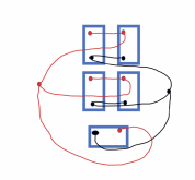
I’m installing 4 12v lithium batteries in parallel. Simple enough to to set them side by side in a row with equal lengths of cable between them. Then attach the main positive cable off one end of the set and the negative off the other end.

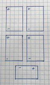
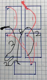
Now, with some rearranging I can add a 5th battery if I need it in the future. With my tray dimensions and the two chassis batteries I would have to place the first four lithiums in side by side pairs and the pairs end on end. Then the fifth one would be placed 90° to the other four and off the end of one pair. Looking at the shortest lengths to the posts gives two 6“, one 10” and one 11 or 12” length for the positive cables and the same for the negative. If I make the cables equal length they will all be 11 or 12” with the ones between the posts on the side by side batteries having a very large curve to them and possible large side force on the terminals.

So, do I need to go with equal lengths cable with a lot of excess of it or size the cable to the distance between corresponding posts making them only as long as necessary for each distance between terminals?

Thanks
 
The cables paralleling batteries need to be the same length between batteries. batteries 1, 2 and 3 could be right next to each other with very short cables paralleling them. Battery 4 could be 2' away with both leads 2' long attaching to battery 3. No need to tweak the other cables.

You should be able to bend/shape the cables to eliminate any side loads.

The main cables that attach to the battery bank (-) and (+) terminals may be of different lengths.

Something like this is fine:

1609826350578.png

The goal is for both parallel paths forming the main terminals to have the same series resistance. If they don't, the load won't be distributed evenly between the batteries.

Link #2 in my signature: "Wiring" for best practices.
 
The cables paralleling batteries need to be the same length between batteries. batteries 1, 2 and 3 could be right next to each other with very short cables paralleling them. Battery 4 could be 2' away with both leads 2' long attaching to battery 3. No need to tweak the other cables.

You should be able to bend/shape the cables to eliminate any side loads.

The main cables that attach to the battery bank (-) and (+) terminals may be of different lengths.

Something like this is fine:

View attachment 32206

The goal is for both parallel paths forming the main terminals to have the same series resistance. If they don't, the load won't be distributed evenly between the batteries.

Link #2 in my signature: "Wiring" for best practices.
I would not think that would work well. The Wiring Unlimited resource you linked to had this pic:

1609827633530.png
(This is page 19.... but the discussion before page 19 is also important to read.

The key is to try to make the round trip resistance from the inverter to each battery and back the same for all 4 batteries in order to balance the wear on the batteries (or cells).

The 'diagonal' layout is ok, but certainly not the best of the 4. For this layout It is important to keep the connections between the wires as short as reasonable and as identical as reasonable.

'Busbars' is just 'diagonal with very big conductors. However, if the bus bars are big enough the resistance becomes so low the differences are inconsequential.

Posts is very good if all of the wires between the posts and the common points are the same. If some of the interconnects are longer than others it throws things out of wack.

Halfway is very good but the short wires between battery posts must all be the same and the longer wires connecting the groups of 2 need to be the same.

In all 4 cases, the wires from the inverter to the first place they connect to the battery bank don't have to be the same size. However, it is always good to keep them as short as possible.

One thing to note: The crimps on the lugs for the wires are just as important as the lengths of the wires. A bad crimp can add more resistance than several feet of wire. The same is true for the connection to the battery... a bad connection can/will throw everything out of balance.
 
Is it optimal? No. is it better than having two different cable lengths between batteries 3 and 4, way. Yes, ideally, he should increase the length of all interconnects to be the same length, but personally, I wouldn't UNLESS, this bank is subjected to routine high current. I should have qualified it that way.
 
I just re-read the original post. I did not understand the description of the layout, but I realized he is asking about a situation with 5 batteries....

The 'diagonal' works ok for 3 or 4 batteries, but the more batteries added the less optimal it gets.
The Halfway needs the symmetry of 4 batteries so it would not work at all for 5 batteries.
The 'Posts' works well for any number of batteries but uses a lot of extra cable to keep things balanced.
The Busbars can work well if the bus-bars are big enough. However, it assumes the jumpers from the busbar to the battery terminal are all the same so in the OP's case it might get back to having extra cable that has to be tucked in.

As @snoobler said.... the importance of this is in direct relationship to the amount of current that is flowing in relation to the size of the wires. If you have 1/0 cables and never run more than 20 amps.... none of this matters. If you run 150 amps, it can start to make a difference.

One big mitigating factor: This is all about making the batteries last longer. With lead acid batteries, 400 cycles was the max you could expect so batteries would wear much faster and keeping the wear even was a lot more important. With LiFePO4, the expectation is that the batteries can cycle 4000-6000 times.... and even then they are supposed to still have 80% capacity..... If one of the batteries wears a bit faster than the others does it really matter?
 
I've used FLA Banks in Parallel and others as well... Many lessons learned and all covered in the Victron Doc.
I've built my LFP Bank using Busbars.
Each battery cable (-) & (+) are equal length to the busbars.
The Shunt is located on the (-) Line for each battery for battery specific data.
A "Master" Shunt resides between the batteries & SCC/Inverter to provide Full System data such as "Battery Bank" voltage, SOC etc.
Each battery has a Fuse on it's (+) Terminal. I use MRBF Fuses
Each battery also has it's own BMS (Chargery BMS8T) and a QNBBM-8S Active balancer as well. *DeliGreen owns QNBBM now and their vendor support SUCKS!"

Uniquenesses:
I use ONLY Royal Excelene 4/0 Fine Welding Wire
My Battery to Bus Bar runs are 5' / 1.524m long, from BusBar to DC E-Panel then to Inverter is another 8'. So I sized to negate any derration and to be able to handle 300A comfortably.

Observed during operation:
The four battery packs in the LFP bank (2x 280AH & 2x 174AH) do share load & charge quite evenly.
The smaller capacity packs will reach full before the larger packs. This results in BMS kicking off for High Volt Disconnect. That just transfers more juice at the bigger batteries.
It is more complicated to manage / control an Inverter or Solar Controller and so a few extra things need to be accounted for in the design & planning stage. Depending on the BMS chosen, it can be either easier or more complicated. Beyond 4 packs in a bank, some form of intermediary manager for the BMS' needs to be in place for ease of control & management.

See the links in my signature for further information & details.
Hope it helps, Good Luck.
Steve_S
 
I apologize, should have added this to the original post for clarity. I think my questions have been answer but this might help if there is more information.

I will be using 2/0 wires.

Many thanks to you all.
Ed
 

Attachments

  • 06E92481-100F-48E1-A575-72065BBF0B03.jpeg
    06E92481-100F-48E1-A575-72065BBF0B03.jpeg
    85 KB · Views: 132
Hmm... you basically have 4 different sizes of interconnects.

View attachment 32231

Battery 5 is not to scale relative to the others. 4 can easily be made the same length as #2 if you shift the battery to be in-line with that terminal if space permits.

Essentially, my prior comments apply. Make 3 and 4 the same length and consider it close enough. If you want perfect, make them all the same length.
Your right about scale. I miscounted the squares on battery 5. I’m not quite following the lines. Where is the positive connection for the top two batteries. Same for positive and negative ones for the middle. And what does cable 2 connect? Negative to negativ, I assume and not the positive of the middle left battery. I believe you were trying to simplify things and only show the relevant cables. But it’s a little too simple for me.

Thanks
 
Yes. I was showing only the relevant connections. 2 is (-) to (-) and 3 was wrong:

1609888539381.png

1 are the 4 interconnects between the 2 evenly spaced pairs.
2 are the interconnects that join the 2 evenly spaced pairs and the one terminal of the "odd" battery.
3 is the "odd" battery (-) interconnect and should be the same length as #2.

Ideally, all interconnects shown should be the same length. Since you already have 4 batteries installed, at a minimum 2 & 3 should be the same length.

I've circled the main terminals you should use. You could flip the (-) and (+) if that works better.

Hope that unmuddies the water a little.
 
What about the option of two strings of two batteries with each pair wired "diagonal"? Then equal length cables from each pair to a cable post or busbar to bring the two pairs together. Then wire the 5th battery as a single and make the cable lengths the same length as the any one battery in a pair.
 
What about the option of two strings of two batteries with each pair wired "diagonal"? Then equal length cables from each pair to a cable post or busbar to bring the two pairs together. Then wire the 5th battery as a single and make the cable lengths the same length as the any one battery in a pair.
MS paint is your friend because I understood nothing of that.
 
I think Carl is suggesting something like this, where each numbered cable is the same length:

06E92481-100F-48E1-A575-72065BBF0B03.jpeg
 
Equal length, or MASSIVELY oversized wiring. Think 550KCmill... or thick bussbars.

i think this arrangement would balance the loads fairly well...
 

Attachments

  • 6F8A77F2-FC32-4E96-8A02-B8EE494C6D60.jpeg
    6F8A77F2-FC32-4E96-8A02-B8EE494C6D60.jpeg
    173.3 KB · Views: 37
I was actually suggesting this. Four of the batteries are wired as pairs with the positive cable and negative cables starting at different batteries in the pair as is normally done when wiring batteries in parallel. While some batteries will have a longer red cable and some batteries have a longer black cable - if you add the lengths of the black and red cables together for each battery it will be the same number. The single 5th battery red and black cables lengths when added together will also be that same number. This way each battery should have the same resistance from cables. I apologize that the lengths of the cable drawn in my drawing are not accurate.
 

Attachments

  • Screen Shot 2021-04-14 at 8.55.32 PM.png
    Screen Shot 2021-04-14 at 8.55.32 PM.png
    134.1 KB · Views: 27
I feel like I'm missing something. I'm a noob, so this is very possible. All the "diagonal" suggestions made so far, other than the Wiring Unlimited reference, seem functionally the same as the diagram in post #2. That is, unequal interconnect lengths but the round-trip length to any one battery in the bank is the same. So is that standard "OK"?
 
Round trip cable length is not the only factor. The more amps on a cable the greater the resistance in that cable. So shared battery interconnects have higher resistance. Batteries in the middle of a string charge/discharge more than batteries at end of the string. Here's a piece where they calculated the difference. http://www.smartgauge.co.uk/batt_con.html
 
Round trip cable length is not the only factor. The more amps on a cable the greater the resistance in that cable. So shared battery interconnects have higher resistance. Batteries in the middle of a string charge/discharge more than batteries at end of the string. Here's a piece where they calculated the difference. http://www.smartgauge.co.uk/batt_con.html
No..... the resistance in the cable does not change with more current... The voltage drop and energy loss does.

Ohms law.
Voltage = Current * Resistance
This means the voltage drop will increase linearly with current increase

Watts law:
Power = Voltage * Current
With a little algebra and combining Watts law with ohms law
Power = (Current * Resistance) * Current = Current^2 * Resistance
This means power loss will increase exponentially with current increase.
You're, of course, right. "Resistance" was the wrong word
 
Great info, and from one Canuck to another, hi... cool to see us on here...... question, and you probably addressed it elsewhere so forgive me if you did...

Do you not have any over current/short protection on the run between the batteries, or battery switch up to the circuit breaker I point out here? Is that the only protection on the battery side? I see contactors on the bank on the right, shunts, bus bars and the switch and a lot of cable, I was always under the believe to protect as close to the battery as possible to protect the cable and maybe you just didn't document them in the diagram. Am I missing something or are you just brave and have good fire insurance... lol

DISREGARD!!! I just noticed your comment "Each battery has a Fuse on it's (+) Terminal. I use MRBF Fuses" they just aren't shown in the schematic....

Jen

1619288682610.png
 
Back
Top