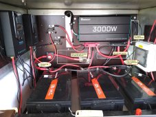
Hello, 4 of my 2/0 cables gets warm to hot like 80 degrees or so, even blew the 300amp anl fuse. The 2/0 cable from the battery positive to the battery cutoff switch
doesn't even get warm, cutoff switch doesn't get hot. The 2/0 cable from the negative busbar to the inverter get pretty warm but from the negative side of the battery
to the busbar doesn't. The inverter get pretty warm like 80-90 degrees also but I'm not sure how hot they get normaly.
I have 600ah of batteries and 800 watts of solar 400w on each controller, 1 has 4 renogy 100w panels series/parallel the other has 2 200w hightec panels in series.
I haven't tried turning off the solar (not that is should matter, I think) and use the inverter and batteries to see if the cables still gets hot.
The inverter it's self has 2 grounding wires hooked to it a 10 gauge and even a 6 gauge battery cable. None of the other cables even get close to warm.
The setup is for a 50amp RV, the 3 wire output of the inverter is running to a 50amp transfer switch on the generator side and hot leg 1 is jumpered to hot leg 2.
The transfer switch doesn't seem any hotter on the generator than the shore power side. I'm not running any a/c's or big amp draws at the same time or anything but
after a few hours the cables get hot and the anl fuse smells like it's burning. Is the 300amp anl fuse too small, I ordered a few 300amp anl fuses and even
an extra 400amp fuse also. Does anyone have any ideas why only those 4 cables and fuse gets hot???
Thank You!!!