diy solar

diy solar

My 24v 24kw Blueprint

2000 watt inverter / 24 volt system * .85 inverter efficiency * 1.25 OCP fudge factor = 88.5 amps. OCP protection of 120 amps is perhaps a bit high, but not bad.

The 1.25 OCP (Over Current Protection) fudge factor is to get the fuse or breaker 25% over what the expected amperage on the wire is, without causing nuisance trips. If we ignored that, you might put in a 70 amp breaker and every time the inverter hit 2,000 watts, the breaker could trip.
 
2000 watt inverter / 24 volt system * .85 inverter efficiency * 1.25 OCP fudge factor = 88.5 amps. OCP protection of 120 amps is perhaps a bit high, but not bad.
Slight mistake in there. It should be 2000W / 24V / 0.85 * 1.25 = 122A. You need to divide by 85%, not multiply.
 
Hi,
Thanks for the feedback! First of all just letting you know I'm very new to this so if I say something silly feel free to correct me. Btw I'm building a 24v system. Below are my answers and questions.

  1. why is it redundant to have fuse and breaker on the positive side? What will be a more efficient setup? The 250v Class T fuse protects the wires to the batteries and the batteries. 40A fuse for the 40A DC24V to DC12V converter. 50A breaker is for the 40A solar controller. 120A breaker is for the 2000w inverter
  2. yes its 6AWG from the controller to the batteries
  3. 2AWG from inverter to batteries
  4. yes, it is a 120a breaker going from inverter to batteries. something wrong?
1. There is no issue with a fuse and a breaker on the same side. It is not really needed. Fuse is for safety for the wire and your breaker can be used as a disconnect switch. Really is not a negative, just saying really both are not needed. Some use a fuse with a disconnect switch. Either way it is ok.
2.# 6 is ok
3. 2 awg from your batteries to your inverter is ok. If you expand your battery bank / inverter in the future, you will have to increase your wire size or just double your wires from 2 to 4. It will depend on how many amps you will be drawing from your batteries to your inverter at a particular time. More amp draw, larger wire size.
4. the 120 amp breaker is ok at this point. 2-12 batteries wired in series is still 100 AH but at 24 volts. It will still depends how how many amps you try to draw at one time. With a 2000 watt inverter pulling 24 volts at a time should restrict you to appx 84 amps before your inverter trips so the 120 amp breaker is ok.
 
1. There is no issue with a fuse and a breaker on the same side.
Which fuse and breaker do you mean? I don't see any redundant uses in the setup.

3. 2 awg from your batteries to your inverter is ok. If you expand your battery bank / inverter in the future, you will have to increase your wire size
Increasing battery capacity (I assume that's what you mean by "expand your battery bank") will not require bigger wire. Installing a larger inverter will.
 
Which fuse and breaker do you mean? I don't see any redundant uses in the setup.


Increasing battery capacity (I assume that's what you mean by "expand your battery bank") will not require bigger wire. Installing a larger inverter will.
1.He has a 125 amp fuse and a 125 amp breaker in line from his inverter to the positive side of his battery.
3. That is why I said battery/inverter. A lot of the time when someone is expanding their setup with more storage they also increase their inverter size. But you are correct, if he only increases the size of his battery bank, no larger wires are needed.
 
He has a 125 amp fuse and a 125 amp breaker in line from his inverter to the positive side of his battery.
There's the main Class-T fuse at the battery. That's good. Then each device has a fuse or breaker. That's good.

Why single out the inverter? It sounds like you are saying that the breaker at the inverter isn't needed because the battery has a fuse. But then why not say the SCC doesn't need a breaker, etc.? I'm honestly curious why you think the inverter breaker is redundant. To me, each fuse/breaker is protecting that stretch of wire. I like to think of it as any wire coming off of the positive bus bar should have a fuse or breaker.
 
I am not signaling out the inverter, I was referring the one positive feed wire from the battery to the inverter. I only said that normally you put a fuse or a breaker to protect a wire and then a cutoff switch. If you want to use a fuse and use the breaker as a cutoff switch, that is fine. The breaker and the fuse both protect the wire. By his drawing , there are no other energy feeds between the battery and the inverter. If you wish you can put multiple fuses and breakers on each wire. I don't understand why some one would do it but it can be done. And yes, I would fuse or put a breaker on each feed wire from the buss bar to feed appliances. We are in agreement.
 
The reason I could see for both fuse and breaker would be for battery protection: e.g. a 100A, 2000AIC breaker that's probably a lot cheaper than 100A, 20,000AIC breaker, but risks sustaining a dead short arc, and a 125A Class T fuse that should never blow, but will definitely kill a dead short from the batteries. Doesn't matter if the fuse allows a bit more current than the wires can safely carry, as the breaker guards against that. I haven't yet started pricing for my system, so maybe this isn't cost effective.
 
10AWG on the output side is fine given how short it is. 12AWG on the input side should be fine since that will be under 25A. I have the same basic DC-DC converter. I cut the supplied leads as short as possible and butt spliced 10AWG to that.

The real trick is to avoid ever actually trying to pull 40A from the converter. If it was a 40A Victron Orion then I would say you could pull 40A all day just fine. But one of these cheap converters may not be able to handle the full 40A very long.
Hi rmaddy,

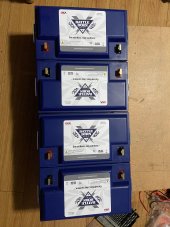
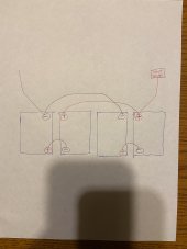
Can you take a look at my attached battery configuration? Thanks!
 

Attachments

  • 0D8F32DA-AEC3-4511-9D50-29884225C73E.jpeg
    0D8F32DA-AEC3-4511-9D50-29884225C73E.jpeg
    167.6 KB · Views: 5
  • A622588F-AB9A-4306-AF44-FA45882EA499.jpeg
    A622588F-AB9A-4306-AF44-FA45882EA499.jpeg
    109.2 KB · Views: 5
I have a similar GIANDEL 24v 2000w square wave inverter. It's pretty old and has a built in PWM solar charger.

Inside of it, after unscrewing it, there are two 30A regular car fuses. It was not in the manual. One time it stopped working and I thought I destroyed it, but turns out I just needed to replace the fuse.

Not sure if yours, the newer version of mine, has the same two fuses but if it stops working, check for fuses. Or I could be a dummy and they put them on the outside now.

Love mine. its a beast can't believe how much crap I throw at it and it still goes on. I think it was the cheapest one on amazon at the time. It has built in OCC and other fault. It beeps a lot. It auto restarts after a delay on failures. The built in solar charger stays on when turned off. When maximum voltage is reach on the battery, it starts up automatically. I had it in a water proof box in the middle of the forest and did all sorts of horrible things to it and it kept going. Basically it would just turn on around 9am and turn off around 10pm. I put almost no thought into it, it was a backup setup.
 
Last edited:
I have a similar GIANDEL 24v 2000w square wave inverter. It's pretty old and has a built in PWM solar charger.

Inside of it, after unscrewing it, there are two 30A regular car fuses. It was not in the manual. One time it stopped working and I thought I destroyed it, but turns out I just needed to replace the fuse.

Not sure if yours, the newer version of mine, has the same two fuses but if it stops working, check for fuses. Or I could be a dummy and they put them on the outside now.

Love mine. its a beast can't believe how much crap I throw at it and it still goes on. I think it was the cheapest one on amazon at the time. It has built in OCC and other fault. It beeps a lot. It auto restarts after a delay on failures. The built in solar charger stays on when turned off. When maximum voltage is reach on the battery, it starts up automatically. I had it in a water proof box in the middle of the forest and did all sorts of horrible things to it and it kept going. Basically it would just turn on around 9am and turn off around 10pm. I put almost no thought into it, it was a backup setup.
Thanks for letting me know!
 
That seems correct for a 2S2P (24V) setup.
Hi rmaddy,

Im trying to optimize the epever mppt 40a solar controller right now with my battle borns. I’ve been watching Will’s video (link shown below) but its only for a 12v battle born. Should i just select “sealed” or “user”. And if select “user” below are the changes he’s made for one 12v battle born. What are the changes i have to make for my 4 battle born 24v system?


For a 12v battle born per Will’s video:
Select “Sealed” OR
Select “ok” and hold it down to select“user”
If “user”:
Temperature compensation coefficient:
Change: -3mv/C/2V to 0mv/C/2V
Charge limit:
Change: 15v to 14.6v
Float charge:
Change: 13.8v to 13.6v
Equalize time:
Change: 120 min to 000 min

Also do i need to do any sort of software setup for my Giandel 24v 2000w inverter as well?

Thanks!!
I run battleborn batteries. This information is supplied from battleborn.
User Settings
Update for Case SUP21927 - "New Inquiry Battleborn Batteries - 2022-01-06 14:50:02"

Good evening,

I listed the EPever settings below:


Battery Charging SettingUser 12 volt/ User24 volt 4-batteries
Also use 200 AH setting for 4 batteries at 24 volt
Over voltage disconnect voltage14.7V / 29.4
charging limit voltage14.6V/ 29.2
over voltage reconnect voltage14.6V/ 29.2
Equalize charging voltageOff or 14.4V/ Off or 28.4
Boost charging voltage14.4V / 28.4
Float charging voltage13.6V/ 27.2
Boost reconnect charging voltage13.3V/ 26.6
Low voltage reconnect voltage12.0V/ 24
Under volt. warning volt11.5v or Off/ 23
Low volt. disconnect volt.11.0v/ 22
Discharging limit voltage10.5 or Off/ 21 or off
Equalize duration (min)Off/ off
Boost Duration (min.) 30 minutes per 100Ah battery bank30/ 60 (2P/2S)
 
Last edited:
I run battleborn batteries. This information is supplied from battleborn.
User Settings
Update for Case SUP21927 - "New Inquiry Battleborn Batteries - 2022-01-06 14:50:02"

Good evening,

I listed the EPever settings below:


Battery Charging SettingUser 12 volt/ User24 volt 4-batteries
Also use 200 AH setting for 4 batteries at 24 volt
Over voltage disconnect voltage14.7V / 29.4
charging limit voltage14.6V/ 29.2
over voltage reconnect voltage14.6V/ 29.2
Equalize charging voltageOff or 14.4V/ Off or 28.4
Boost charging voltage14.4V / 28.4
Float charging voltage13.6V/ 27.2
Boost reconnect charging voltage13.3V/ 26.6
Low voltage reconnect voltage12.0V/ 24
Under volt. warning volt11.5v or Off/ 23
Low volt. disconnect volt.11.0v/ 22
Discharging limit voltage10.5 or Off/ 21 or off
Equalize duration (min)Off/ off
Boost Duration (min.) 30 minutes per 100Ah battery bank30/ 120
cool. thanks!
 
Hi rmaddy,

Im trying to optimize the epever mppt 40a solar controller right now with my battle borns. I’ve been watching Will’s video (link shown below) but its only for a 12v battle born. Should i just select “sealed” or “user”. And if select “user” below are the changes he’s made for one 12v battle born. What are the changes i have to make for my 4 battle born 24v system?


For a 12v battle born per Will’s video:
Select “Sealed” OR
Select “ok” and hold it down to select“user”
If “user”:
Temperature compensation coefficient:
Change: -3mv/C/2V to 0mv/C/2V
Charge limit:
Change: 15v to 14.6v
Float charge:
Change: 13.8v to 13.6v
Equalize time:
Change: 120 min to 000 min

Also do i need to do any sort of software setup for my Giandel 24v 2000w inverter as well?

Thanks!!
Forgot to mention, no setup on your Giendel inverter.
 
Back
Top