v2.
Introduction
Hi everyone!
I have always spent the summers and part of the winter out in the archipelago it the most northern part of the Bothnian Bay in Sweden (Finland is only a slap shot to the East). During summer time, we get sun 24 hours a day and, conversely, during parts of December and January we get no sun at all, as shown in the below pictures taken at midnight a summer day and at noon on new years eve.

We have previously only had a one panel system, but I always nurtured a dream to get electricity to this place. Sure, there can be a charm in being without it for a month here and there, but living conditions are harsh enough as it is up there.
Disclaimer / Important Message
Before I continue, I want to be overly clear that I am not an electrician. Not an engineer in any way. I am a business lawyer that is somewhat handy and that has worked extra as a carpenter and stuff like that, but I have very little experience wiring cables. My system has not really been reviewed by anyone knowledgeable. I have noticed how I made some wiring that potentially could have been dangerous and of course fixed those issues, but there is definitely no guarantee that any part of my build is not faulty and hence dangerous. Do not do anything I have done, at least if you cannot verify yourself that is 100% correct.
Step 1 -- Choosing Gear and drawing a Blueprint vs. my Budget (app. 6,000 USD)
Choosing the Battery, and drawing the Blueprint
My first step was to build a blueprint and choosing the necessary gear. I had (barely) a 6k USD budget this, and depending on the alternatives I looked at, I was first looking at dividing my build over 2 years, mainly to first get the inverter and cells and then add batteries from Pylontech next summer. But especially due to the inspiration I got from Andy's Off-Grid Garage and the safety I could feel in ordering cells from China due to the references at this place, I decided to go with a DIY 48v Powerwall Option.
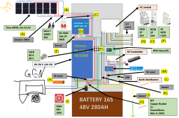
After the battery was in place, I just built the blueprint from that. At first, I really fumbling in the dark. Its funny how a certain thing that just feels like a 100% given today, was a complete mystery just a few months ago. Take an aspect like how the cable from the Solar Charge Controller/MPPT (hereinafter "SCC") can go into a T-junction with one end going into the battery and the other to the inverter was never something I would have figured out myself.
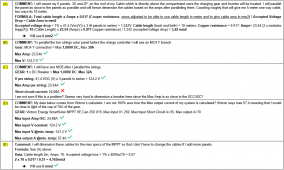
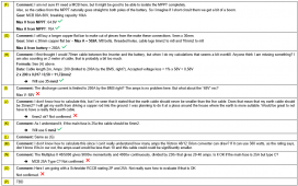
I made my blueprint in PowerPoint and after I to a larger extent had everything in place, I realized that I was just guessing every step of the way on which size of breakers, fuses, cables and what not that I needed -- I created a separate document in which I made the calculations myself. That was actually a really easy part of everything, since the math itself is 100% "googable". The parameters comes from the gear, how many amps can the SCC put out? Then you just need to google how to calculate the size of the cable which can handle that load. Then it was the same with fuses/MCBs.
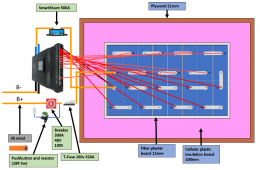
This is my blue-print and how it looked right up until my ordering of the gear started. I actually just ruined my laptop which it was saved on, so its not updated, but like 95% correct. I have not implemented the 48v to 12v function, but instead got a 12v charger on AC out 2 and the old 12v system is kept alive.
Victron vs. Others
One choice I had to make was to go with Victron or Growatt or another solution (some US alternatives does not seem to really be available in Europe, I see you guys talk about some options that I never see for sale here). My Victron Multiplus II 48/5,000 Hybrid Inverter (it can invert DC to AC and charge the battery with DC from for example an AC petrol generator, hereinafter "MP2") cost about 1,750 USD and my 150/60 SCC cost around 600 USD. I could probably have saved up towards 50% with other alternatives. I went with Victron. I do not know if that was a wise decision. But I can say this, everything have worked. I have this old battered petrol inverter providing an awful quality AC output, but after adjusting the settings, it works. Everything connects. When you want to do something, sure enough there is a built in function for it.
I am very "China" friendly when ordering gear, often its as high quality as the products built and sold in Europe, and in fact, products built and sold in Europe/the US can be very over priced and under-developed. In this case I am sure there are very good alternatives from China, but I have no objections against the Victron gear. Its quality as far as I can tell.
Fuses, breakers, and connections/junctions
I was myself interested in getting links to the fuses, MCBs and junctions other used, but after a while I abandoned that completely. Especially when I started ordering stuff, and my first alternatives were out of stock or seemed very expensive. All you need to have are the specs, which I got from my above calculations, then you can just google like "MCB DC 500V 16A" or whatever.
As for the junctions, connection boxes, fuse holders and what not -- these things are the first thing you can save money on. Get a copper bar, 6 feets or whatever, drills and gear to make threads. A small piece of a copper bar with three holes in it is a T-junction. Some connections will be M10, others M8. Some busbars constructions can easily cost 100-150 USD, and can be made DIY for a 1/10 of that.
The Cells
My sells came from Jenny Wu and were in mint condition on the outside. I did not test them, nor did I balance them before hooking them up to the JK BMS.
Step 2 -- The Mounting of the Gear exkl. of Panels
The Gear except the Panels
I mounted everything on a temporary "wall", about 80x140CM, and then brought the entire wall with me. The wall is made of wood covered with a painted plaster board and covered by a frame on which I have mounted a door of acrylic glass. I used left over hinges from an IKEA wardrobe and have cut holes in the acrylic gear so that I can access what should be accessible fast as well as to provide ventilation for the SCC and MP2.
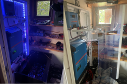
My (not so) Tidy Wiring
I tried to wire everything as tidy as possible, but after smaller adjustments had to be made and everything was added -- it got darn hard to make it look professional. I mention this because if I wouldn't have been careful from the start, thinking everything would be super organized, the end product would have been a complete mess instead of what I have now that is just a bit messy.
Crimping Gear, cable lugs etc
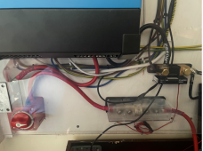
I used my own crimping gear for all smaller cables, but ordered pre made 35mm2 cables with M8 lugs. I regret that. The shortest pre-made cables I could get was 30 cm, sometimes 10 cm would have been better.
This shows the downside with not being able to choose your own length of the cables as well as how messy things have gotten at the end:
Step 3 -- The mounting of the Panels
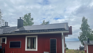
My budget was wiped out by the gear I bought, so I had to mount the panels using 'leftovers'. We had some aluminium stuff lying around from a small loading dock, which I put on the roof and locked panels too.
This is how it ended up looking, not super pretty but hey, it didn't cost me a cent (below the roof, you can see my two old panels for the 12v car battery system, which have been up and running for like 20-30 years now...):
Introduction
Hi everyone!
I have always spent the summers and part of the winter out in the archipelago it the most northern part of the Bothnian Bay in Sweden (Finland is only a slap shot to the East). During summer time, we get sun 24 hours a day and, conversely, during parts of December and January we get no sun at all, as shown in the below pictures taken at midnight a summer day and at noon on new years eve.

We have previously only had a one panel system, but I always nurtured a dream to get electricity to this place. Sure, there can be a charm in being without it for a month here and there, but living conditions are harsh enough as it is up there.
Disclaimer / Important Message
Before I continue, I want to be overly clear that I am not an electrician. Not an engineer in any way. I am a business lawyer that is somewhat handy and that has worked extra as a carpenter and stuff like that, but I have very little experience wiring cables. My system has not really been reviewed by anyone knowledgeable. I have noticed how I made some wiring that potentially could have been dangerous and of course fixed those issues, but there is definitely no guarantee that any part of my build is not faulty and hence dangerous. Do not do anything I have done, at least if you cannot verify yourself that is 100% correct.
Step 1 -- Choosing Gear and drawing a Blueprint vs. my Budget (app. 6,000 USD)
Choosing the Battery, and drawing the Blueprint
My first step was to build a blueprint and choosing the necessary gear. I had (barely) a 6k USD budget this, and depending on the alternatives I looked at, I was first looking at dividing my build over 2 years, mainly to first get the inverter and cells and then add batteries from Pylontech next summer. But especially due to the inspiration I got from Andy's Off-Grid Garage and the safety I could feel in ordering cells from China due to the references at this place, I decided to go with a DIY 48v Powerwall Option.
After the battery was in place, I just built the blueprint from that. At first, I really fumbling in the dark. Its funny how a certain thing that just feels like a 100% given today, was a complete mystery just a few months ago. Take an aspect like how the cable from the Solar Charge Controller/MPPT (hereinafter "SCC") can go into a T-junction with one end going into the battery and the other to the inverter was never something I would have figured out myself.
I made my blueprint in PowerPoint and after I to a larger extent had everything in place, I realized that I was just guessing every step of the way on which size of breakers, fuses, cables and what not that I needed -- I created a separate document in which I made the calculations myself. That was actually a really easy part of everything, since the math itself is 100% "googable". The parameters comes from the gear, how many amps can the SCC put out? Then you just need to google how to calculate the size of the cable which can handle that load. Then it was the same with fuses/MCBs.
This is my blue-print and how it looked right up until my ordering of the gear started. I actually just ruined my laptop which it was saved on, so its not updated, but like 95% correct. I have not implemented the 48v to 12v function, but instead got a 12v charger on AC out 2 and the old 12v system is kept alive.


Victron vs. Others
One choice I had to make was to go with Victron or Growatt or another solution (some US alternatives does not seem to really be available in Europe, I see you guys talk about some options that I never see for sale here). My Victron Multiplus II 48/5,000 Hybrid Inverter (it can invert DC to AC and charge the battery with DC from for example an AC petrol generator, hereinafter "MP2") cost about 1,750 USD and my 150/60 SCC cost around 600 USD. I could probably have saved up towards 50% with other alternatives. I went with Victron. I do not know if that was a wise decision. But I can say this, everything have worked. I have this old battered petrol inverter providing an awful quality AC output, but after adjusting the settings, it works. Everything connects. When you want to do something, sure enough there is a built in function for it.
I am very "China" friendly when ordering gear, often its as high quality as the products built and sold in Europe, and in fact, products built and sold in Europe/the US can be very over priced and under-developed. In this case I am sure there are very good alternatives from China, but I have no objections against the Victron gear. Its quality as far as I can tell.
Fuses, breakers, and connections/junctions
I was myself interested in getting links to the fuses, MCBs and junctions other used, but after a while I abandoned that completely. Especially when I started ordering stuff, and my first alternatives were out of stock or seemed very expensive. All you need to have are the specs, which I got from my above calculations, then you can just google like "MCB DC 500V 16A" or whatever.
As for the junctions, connection boxes, fuse holders and what not -- these things are the first thing you can save money on. Get a copper bar, 6 feets or whatever, drills and gear to make threads. A small piece of a copper bar with three holes in it is a T-junction. Some connections will be M10, others M8. Some busbars constructions can easily cost 100-150 USD, and can be made DIY for a 1/10 of that.
The Cells
My sells came from Jenny Wu and were in mint condition on the outside. I did not test them, nor did I balance them before hooking them up to the JK BMS.
Step 2 -- The Mounting of the Gear exkl. of Panels
The Gear except the Panels
I mounted everything on a temporary "wall", about 80x140CM, and then brought the entire wall with me. The wall is made of wood covered with a painted plaster board and covered by a frame on which I have mounted a door of acrylic glass. I used left over hinges from an IKEA wardrobe and have cut holes in the acrylic gear so that I can access what should be accessible fast as well as to provide ventilation for the SCC and MP2.

My (not so) Tidy Wiring
I tried to wire everything as tidy as possible, but after smaller adjustments had to be made and everything was added -- it got darn hard to make it look professional. I mention this because if I wouldn't have been careful from the start, thinking everything would be super organized, the end product would have been a complete mess instead of what I have now that is just a bit messy.
Crimping Gear, cable lugs etc
I used my own crimping gear for all smaller cables, but ordered pre made 35mm2 cables with M8 lugs. I regret that. The shortest pre-made cables I could get was 30 cm, sometimes 10 cm would have been better.
This shows the downside with not being able to choose your own length of the cables as well as how messy things have gotten at the end:

Step 3 -- The mounting of the Panels
My budget was wiped out by the gear I bought, so I had to mount the panels using 'leftovers'. We had some aluminium stuff lying around from a small loading dock, which I put on the roof and locked panels too.
This is how it ended up looking, not super pretty but hey, it didn't cost me a cent (below the roof, you can see my two old panels for the 12v car battery system, which have been up and running for like 20-30 years now...):

Last edited:


