diy solar

diy solar

My adventures building a Zinc-Bromine battery

I ordered some Sodium Bromide and Zinc Sulfate in order to test an electrolyte comprised of Zinc Bromide, saturated with Sodium Sulfate plus 20% PEG-200. Sodium sulfate is known to reduce the edge formation of Zinc dendrites (see here) so this seems like a nice experiment to test a much cheaper electrolyte that can also help with the formation of dendrites. The electrolyte is much cheaper because both NaBr and ZnSO4 are available in kilogram quantities for low amounts of money (compared to Zinc bromide, which is much more expensive at small scales).

In order to prepare the electrolyte I plan to prepare a solution with 6M NaBr + 3M ZnSO4 + 20% PEG-200, this will give me the 3M ZnBr2 I need but will be above the solubility limit of NaSO4 at ambient temperature, so I will filter out the solution to remove the precipitated NaSO4. This should serve to reduce the series resistance of the cell and hopefully the dendrites as well. These are experiments for next week though, in the meantime I'll keep on testing my current electrolytes made of 3M ZnBr2.
 
Last edited:
I got a little bit more (10 cycles) before failure due to dendrites.

1603206476809.png
Talking about this with a friend in battery research, it seems that the dendrites can become more of a problem as the electrolyte becomes more depleted and migration becomes harder for Zinc ions. This is part of the reason why dendrites have become a significant issue at these larger energy density values (>20-30Wh/L), because of this, it seems that my idea to use a ZnSO4+NaBr electrolyte might actually be on the right path, as Sodium Sulfate is one of the most studied supporting electrolytes to prevent this from happening.

I also decided to try to saturate some 3MZnBr2+20% PEG solution with common household NaCl (which contains a small amount of iodide as well) to see how well this salt does as a supporting electrolyte while I proceed with the other plan. I'll post some results about this combination as I get them (currently testing with a 10% treated GFE-1 cathode).
 
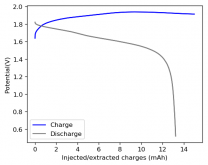
First cycle with a GFE-1 cathode pretreated with 10% TMPhABr and a 3M ZnBr2 + 20% PEG-200 electrolyte saturated with home NaCl.

Charging to 15mAh at 5 mA, discharging to 0.5V. CE = 94.37%. EE=74.60%

1603232482576.png
Energy density is 31 Wh/L. So far very good Coulombic and energy efficiency values, let's see how these efficiences evolve as a function of time and whether this affects dendrite formation or not.Hoping for the best ?
 
Hi, I've watched this thread many times and thank you so much for sharing.
Would it be possible to test the self discharge over a period of a week ?
Yesterday there was a video with similar battery in a channel called Robert Murray however like many other videos there is no data of relevance.
I am using lithium for storage, but keeping an eye on alternatives :)
 
Sadly it didn't even last 4 cycles ☹️ If anything it seems the NaCl made things substantially worse.

1603289304153.png
 
Hi, I've watched this thread many times and thank you so much for sharing.
Would it be possible to test the self discharge over a period of a week ?
Yesterday there was a video with similar battery in a channel called Robert Murray however like many other videos there is no data of relevance.
I am using lithium for storage, but keeping an eye on alternatives :)

Thanks for your support :) I will start testing self-discharge as soon as I find some solution to the Zinc dendrite problem!
 
I'm doing an additional experiment with the remaining saturated NaCl electrolyte, added some PEG to bring the total PEG-200 concentration to close to 30-35%. Just one last experiment before I get NaBr and ZnSO4 so that I can do those experiments instead.
 
Last edited:
Trying to prepare a solution of known ZnBr2 concentration from NaBr and ZnSO4 doesn't seem to be an easy task. The amounts required of both are pretty large and the very large amounts of sodium sulfate formed greatly increases the difficulty of extracting all the solution while maximizing the transfer of ZnBr2. I think the best bet is to actually prepare pure ZnBr2 from this process although water is likely a poor solvent for this as it evaporates too slowly and ZnBr2 is too hygroscopic. Isopropyl alcohol might be significantly better since it can be obtained without much water for cheap, evaporates readily and dissolves relatively large amounts of ZnBr2 while sodium sulfate is practically insoluble in it.

In the meantime I will continue experiments using my pure ZnBr2 source, while I figure out a better process to make larger amounts from these cheap sources of Zn and Br.
 
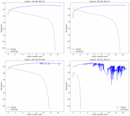
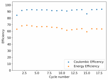
The first separator-less battery has now done 10 cycles. The battery still lives but some signs of Zinc dendrites touching the cathode have started to show up - sudden downspikes in the charging potential in cycle 9 for example - however the battery has so far been able to recover from these spikes.

1603579224296.png
The charging potential seems to be increasing with time and so far the battery has failed to fully stabilize but it is still alive and with CE > 90% and EE > 60%. I want to see how it copes with the dendrite issue and whether it can recover from these problems or fully dies at one point. The absence of a solid separator means that dendrites do not cause irreversible damage. They can also react more easily with flowing bromine/perbromides in the solution so dendrites shouldn't "kill" the battery. We'll see if they can kill it if continuous charging/discharging is done! Stay tuned :)
 
Really cool stuff! Thanks for sharing!
... however the battery has so far been able to recover from these spikes....
What's the mechanism for that? Heat? Are the dendrite tips dissolving? Wondering if you could enhance it on purpose when some pre-condition is met (e.g., capacity < X then run heat cycle) by an external controller.

The charging potential seems to be increasing with time...
Increased surface area from dendrite formation?
 
What's the mechanism for that? Heat? Are the dendrite tips dissolving? Wondering if you could enhance it on purpose when some pre-condition is met (e.g., capacity < X then run heat cycle) by an external controller.

In a separator-less design bromine diffuses more readily, so dendrites tend to be dissolved by self-discharge reactions more effectively (this probably also implies we'll see worse self-discharge when we test this). Note that when they dissolve the battery returns to its original state, while in a separator-containing battery the separator is "pierced" and irreparably damaged by the dendrite, even if it dissolves later on the battery never fully recovers. I am not interested in any battery that requires periodic treatment (either by heat, having to deep discharge, etc) since this greatly complicates battery management and leads to a lot of additional hurdles for success (look at how the memory effect went for Ni-Cd batteries).

Not that I am focused on any sort of commercial development - I am mainly interested in building an understanding - but I understand fellow DIY people who want to build these for solar applications would ideally want something without these issues.

Increased surface area from dendrite formation?
By this I meant that the potential required to charge is increasing, which is a negative and means the internal resistance of the battery is increasing. This can be explained if you think about the fact that the Coulombic efficiency is not 100%, so some charge is never recovered, meaning there are additional potentially non-reversible chemical processes going on (like hydrogen evolution). If any electrolyte is lost to these processes it likely never comes back, so the conductivity of the solution is being depleted and the internal resistance increases. If these processes continue they are likely to kill the battery with time.

Always appreciate your questions and support :)
 
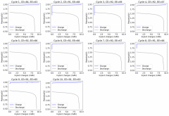
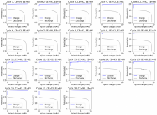
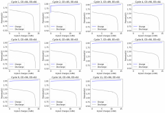
So far 18 cycles have happened without the battery dying:

1603634480267.png
1603634492259.png

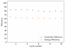
Although some curves do show instabilities typical of dendrites touching the cathode - sudden potential drops on the charge curve - the battery seems to have recovered nicely from these. The charging potential also seems to have stopped increasing and has settled around 2.050V. The CE has settled at ~93% with the EE ~63%. I will continue to cycle to see if we can get to 100 cycles with this configuration :)
 
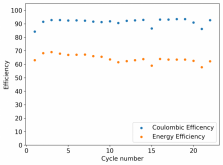
In the end I just ran the battery for 22 cycles, then opened it to see how it looked (was really curious). The battery had absolutely no dendrites when I opened it. It was opened at the end of a discharge cycle (to 0.5V) and no dendrites were hanging from the anode, stuck into the cathode or floating around in the electrolyte. The spacer was slightly discolored though, so it seems the solution was getting to it with time (I will need to change to a carbon/HDPE spacer in the future).

1603667055584.png
The final efficience values were CE=92.73% and EE=62.28% but the battery went through a couple of bad cycle from which it managed to recover to its previous CE and EE values. This was an initial test but the spacer was actually thicker than I would have ideally wanted (~4mm) so I cut it down in half, closer to ~2mm in order to decrease spacing and increase the Wh/L of the battery.

I have now made a new battery with the reduced spacer and will try to charge it to 15mAh at 10mA. So far the charging potential is lower at the same charge density so, so far, so good. If this experiment succeeds we will have a battery with an energy density of 40Wh/L, which I will be satisfied with and we'll start doing self-discharge tests :)
 
I had the idea to use PTFE o-rings as spacers, I ordered some with the exact outer diameter I needed (0.5") from McMaster-Carr. These are 1.77mm thick, so I can stack them to get any spacing size I require while keeping the setup very reproducible. I will build cells with these after I get them, in the meantime I will cycle the cell with the thinner PVC spacer described in my previous post.
 
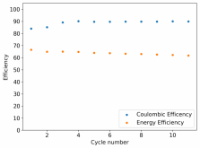
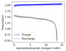
I've now run 11 cycles with this spacer (I made a ~3mm one out of carbon embedded HDPE to prevent reactivity) at 15mA charging to 15mAh, energy density at ~31 Wh/L.

1603808539691.png
1603808572834.png

No evident dendrites despite the higher charge density. I'll keep cycling while I wait for my PTFE separators...
 
As the WP article says:
Drawbacks include:
  • The need to be fully discharged every few days to prevent zinc dendrites that can puncture the separator.[2]
  • The need every 1–4 cycles to short the terminals across a low-impedance shunt while running the electrolyte pump, to fully remove zinc from battery plates.[2]
  • Low areal power (<0.2 W/cm2) during both charge and discharge, which translates into a high cost of power.[3][4][5]
Just curious, how are you circulating the electrolytes, if at all?
 
Danial, Thank you for all the awesome insights so far.

I am super curious about the recent video of Robert Murry using a ceramic separator would be interesting to see if a dendrite could ever plate its way through that structure.

I have also been thinking about applications for even a ZnBr2 cell with high self discharge and i think it would be perfect time shifting power.
In New Zealand and we have 15 minute power pricing so in theory you could build a battery, buy power when its cheaper and use it when its quite expensive. during the day it could charge from solar for the evening peek usage. and again charge over night from very cheap renewable (We have lots of geothermal and hydro) for the morning peeks.

Great work, i cant wait to get my hands on some supplies and have a go my self.
 
As the WP article says:

Just curious, how are you circulating the electrolytes, if at all?

I am not recirculating, this is not a Zn-Br flow battery (the wikipedia page is mainly about this type), this is a static Zn-Br battery. I use a graphite anode for zinc deposition, TMPhABr as a sequestering agent for bromine which is imbedded in a GFE-1 graphitic carbon felt cathode and an electrolyte comprised of ZnBr2 3M, 20% PEG-200. I have used non-woven fiberglass as a separator but because of dendrite issues I decided to move to a separator-less setup where I use PTFE spacers to control the distance between anode and cathode. All my batteries are constructed/measured in a Swagelok cell (0.5 inch internal diameter).
 
Back
Top