diy solar

diy solar

My adventures building a Zinc-Bromine battery

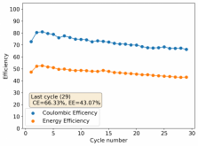
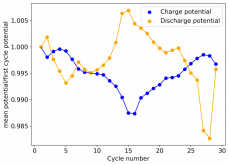
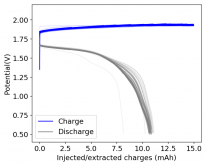
First 29 cycles of an inverted battery (GFE-1 cathode pretreated with 10% TMPhABr on top) using the electrolyte described in #160
1606335534867.png

1606335519514.png
1606335551649.png

Charge and discharge potentials have remained within 2% of their initial values. I want to run this battery for more than 50 cycles to make sure that it will not die before doing additional experiments. Despite the lower CE and EE values, it does seem that an inverted configuration is the only viable one in a stable ZnBr static battery, due to the need to keep hydrogen from escaping the device.

A normal configuration (cathode at the bottom) makes it hard for hydrogen bubbles at the anode to leave or react, making the surface area of the anode decrease with time. If the bubbles escape, then all that hydrogen evolution makes the electrolyte irreversibly more basic, making the pH go higher and higher with time, eventually completely killing the battery (as Bromine is unstable at higher pH values and ZnO forms at the anode surface).
 
I have also been doing some tests of miscibility and solubility with propylene carbonate (PC) which is a polar aprotic solvent that I thought could be used in these batteries. Sadly the solubility of ZnBr2 in PC is not very high (I estimate it to be 0.5-1M at 20C), so making an electrolyte entirely out of PC doesn't seem possible. The solubility of TMPhABr in PC is quite high though, so I thought I could use it in a biphasic system as the cathode. However when you mix it with a ZnBr2 1.5M solution with 1% PEG-200 and 1% Tween it just forms an emulsion (not shocking given the surfactant present), so this didn't seem to work.

I then made a saturated solution of TBABr in PC, which seems to be around ~50% by weight and this solution actually does not mix at all with the ZnBr2 solution. It should be pretty good at conducting charges, so an experiment with a GFE cathode soaked in this PC solution in an inverted cell will be quite interesting. Since the TBABr/PC solution is less dense than water and the TBABr3 really hates water, it should help retain the Br significantly better.

I will be running the current cell (#161) to 50 cycles though, so I will likely do this experiment after thanksgiving ?
 
Hi Daniel, Great work. It reminded me of this article, apologies if you've already seen it, but just in case you haven't. https://iopscience.iop.org/article/10.1149/2.0151816jes
Thanks for linking that article, I have read it before, but I do believe others who haven't will find the link really useful. Given my current experience with these batteries, I now believe that this article ignores some key problematic aspects that greatly limit the usability of a minimal architecture Zn-Br battery. The life cycles in the thousands under realistically high current loads are just not possible once you consider them.

The first is that Titanium current collectors will degrade significantly over time, the second is that a normal architecture with a CE > 90% and an EE > 70% will just not last that long due to deterioration caused by hydrogen evolution, this kills the batteries due to the alkalization of the electrolyte . An inverted architecture that removes this problem then cuts your CE down to 70% and your EE down to 50%, which makes all the numbers much worse.

It does become pretty clear after sometime working in these batteries why the industry decided to go with Zn-Br flow batteries rather than static configurations. The static configurations, even very simple ones, have problems that are quite formidable once you consider real-life deployments and their requirements.
 
Here are some new results using propylene carbonate. I was now able to get a cathode saturated with an organic phase to behave quite efficiently. The fact that lower currents give better CE/EE values points to self-discharge being significantly slower, although this won't be confirmed until I actually measure it.

Daniel, the Chemisting.com is showing a Web error
 
I've been thinking a lot recently about whether it is better to use a non-woven fiberglass separator setup or a PTFE o-ring setup. With the issue of zinc dendrites largely solved by a 1% Tween 20 addition and the use of 1.5M ZnBr2 instead of 3M, it seems that separators might be the better choice. Let me know what you guys think about this latest post.

 
Seems like both have specific use cases (e.g., no O-RIngs for an RV).
(website works fine for me too!)
 
It seems to work fine for me. Let me know if you are still seeing a problem.
Hi Daniel
I am still getting the error.
Other links work fine just Chemisting. This is what I get
 

Attachments

  • Screenshot_20201201-060928.jpg
    Screenshot_20201201-060928.jpg
    26.9 KB · Views: 5
Hi Daniel
I am still getting the error.
Other links work fine just Chemisting. This is what I get
Thanks for letting me know Tim! It might be your phone/browser combination that the page is having issues with. Can you access it without problems from a desktop?
 
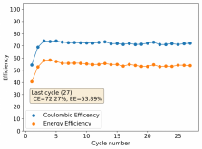
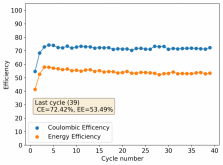
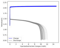
Before continuing with my work with propylene carbonate - which is more time consuming - I wanted to see if the use of a ZnBr2 1.5M + 1% Tween 20 electrolyte makes the use of separators viable and, if this is the case, whether this leads to the first stable configuration that could be built by others at a larger scale. I put together a cell with this electrolyte a GFE-1 cathode pretreated with a 10% TMPhABr solution and a 16 fiberglass separator layer 2 days ago in an inverted configuration (GFE-1 cathode on top). These are the results after 27 cycles, charging/discharging at 15mA to 15mAh of charge and discharged to 0.5V. Energy density at last cycle is 20 Wh/L.

1606845397798.png
1606845422899.png
1606845521315.png
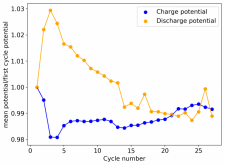
In contrast to previous experiments using fiberglass separators, this experiment has not died or showed any sort of dendrite related deterioration. Mean charge/discharge potentials evolved very positively during the first 5 cycles and have since deteriorated although the pace of deterioration seems to be slowing down and the potentials have not deteriorated past 2% of the mean potentials of the first cycle yet.

I really want to see how far this setup goes, since it has been really stable so far, so I will keep running it until it hits at least 20% deterioration from max capacity or energy density. If it runs for more than 200 cycles without that much deterioration, it could be a good candidate for someone to attempt to build a larger device with the same configuration.

I have given this some thought and I believe a glass petri dish that is 5.9" x 0.75" could be built to use the same configuration with graphite foil as anode at the bottom, 16 layers of the fiberglass separator and a GFE-1 cathode plus a graphite foil current collector at the top. This would give around 5.2Wh of energy with a total amount of charges stored of 3.6Ah.
 
Things don't always go as planned when scaling, it'll be interesting to see what you get!
Love reading your posts!
 
Things don't always go as planned when scaling, it'll be interesting to see what you get!
Love reading your posts!

Thanks a lot for your support :) I sadly don't have the equipment to properly characterize a battery of this size yet! I will probably post the instructions on my blog after the stability and characteristics of this setup are confirmed so that others can try building the petri dish version. I will however try to optimize the setup further and see if I can increase the energy efficiency, which is quite low (~50%) in the inverted configuration.
 
Still going strong after 39 cycles. Charging to 15mAh and discharging to 0.5V at 15mA. Current energy density still above 20 Wh/L.

1606919339929.png
 
Thanks for letting me know Tim! It might be your phone/browser combination that the page is having issues with. Can you access it without problems from a desktop?
Hi Daniel
Works fine on laptop. Still not on phone. Will have to bing read once a week rather than daily on phone.
 
Back
Top