diy solar

diy solar

My battery build for truck camper

Martijn

New Member
Joined
May 6, 2021
Messages
244
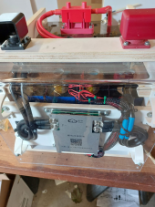
After some discussion in this thread, here's my battery build.

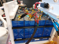
  • bottom plate and end plates: 19mm ply
  • 8 cells currently measuring 25.6v
  • 8mm threaded rods to 'clamp', cells are snug, can't move em by hand
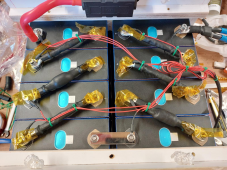
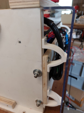
  • .5mm phenolic paper as insulator between cells, while the cells are somewhat clamped, at the bottom and top, there's still some room, about 1-2mm (see photo)
  • about 8mm polycarbonate (now still covered in protective film) above the cells
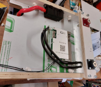
  • BMS will be mounted on the polycarbonate
  • main positive directly to fuse, class T-fuse has been ordered, but I've been told they're are hard to come by currently, so will be replaced later
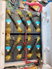
  • cells connected using flexible (braided) cable (50mm2) when going from cell to cell in direction of expansion, 1 solid busbar in non-expansion direction
  • all connections are crimped using hydraulic crimping tool
  • applied conductive paste to all cell connections
  • all balance/monitoring leads tied down, balance leads connected via additional nut if cell post was long enough, if not, directly under flange nut
  • all connections torqued to 5Nm
  • battery-connection positive and battery-connection negative (with covers, not on photo) to be mounted properly later on, from positive to main switch
  • hope to 3d-print some terminal covers later, although the polycarbonate covers the cells
  • additional thinner polycarbonate sheet on top, next to battery-connections, to cover BMS, sides are left open
  • complete battery will be bolted to the floor using 4 m6 bolts
Things I'm (still) worried about:
  1. cell connections loosening up due to vibration
  2. compression or lack thereof ( what is an acceptable 'buldge'?
  3. possible alternative position for BMS, put it on the (open) side next to the main positive/negative connection for less stress on BMS wires?
Any comments or suggestions?

With regards,

Martijn

1659729249444.png
1659729197929.png
1659729441934.png
 
>snip
Things I'm (still) worried about:
  1. cell connections loosening up due to vibration
  2. compression or lack thereof ( what is an acceptable 'buldge'?
  3. possible alternative position for BMS, put it on the (open) side next to the main positive/negative connection for less stress on BMS wires?

Pretty cool. You got some serious power there now.

1. If you're concerned about your terminal nuts, replace them with nylocks.
2. I'm curious about the 'bulge' as well - is that some kind of flex cable or something? Shrink tube didn't shrink?
3. Locate wherever it's convenient.

Does the main bus bar connecting the two banks have matching current carrying as the cell connectors? Visually it appears much smaller in capacity, but without knowing content or dimension it's hard to tell.

I never liked the balance leads on the terminals, but at least you have them on top of the main nuts. Seems you're running out of threads on your studs/grub screws.
 
Your build looks awesome.. you definitely took your time in building it. Well thought out and not just slapped together. Your plywood box is much stronger then any of the plastic battery boxes used. The nylon locking nut would be a great piece mind upgrade.
 
Things I'm (still) worried about:
  1. cell connections loosening up due to vibration
Been doing RV installs for years. You are fine. Just plan on torquing them once a year. Preferably I would use the nuts with the star washers on the bottom. It looks like the flange nuts you have do not have such.

Either way, nice build.
 
Pretty cool. You got some serious power there now.

1. If you're concerned about your terminal nuts, replace them with nylocks.
2. I'm curious about the 'bulge' as well - is that some kind of flex cable or something? Shrink tube didn't shrink?
3. Locate wherever it's convenient.

Does the main bus bar connecting the two banks have matching current carrying as the cell connectors? Visually it appears much smaller in capacity, but without knowing content or dimension it's hard to tell.

I never liked the balance leads on the terminals, but at least you have them on top of the main nuts. Seems you're running out of threads on your studs/grub screws.
1. the welded studs are a bit on the short side for my liking, the main positive, for example, has the balance lead under the flange nut.
2. that bulge is shrink tube not shrunk, it lets the braided wire be more flexible, figured that out after I made almost all of them ;) I was wondering about the slight bulge in the cells in the middle, what is acceptable?
3. will do, figured being able to tighten/check the nuts on the cell posts would be nice. When putting the BMS on top, this becomes harder.

That busbar is 2 bars that came with the cells, stacked together, I'm pretty sure it will do fine.
 
The nylon locking nut would be a great piece mind upgrade.

That's actually a fine idea, as I have those. ;)

One thing I wonder about, with regards to the balance leads, could it go between nut and cell connection then? Because a locking nut would be even thicker than a normal nut.
Been doing RV installs for years. You are fine. Just plan on torquing them once a year. Preferably I would use the nuts with the star washers on the bottom. It looks like the flange nuts you have do not have such.

Either way, nice build.

Alternatively, what about a star washer and a slim nut, with another slim nut on top and the balance lead in between?
 
One of the greatest challenges with any of these battery and system builds are the connections - nearly all voltage drops and heating comes from some kind of interference with them, or corrosion over the long term, or poor crimps, or loosening nuts. So the simpler you make it, fewer dissimilar metals, heavier cabling, the less chance you have for any of these issues.

The main current flow comes from the lug surface to the battery terminal, not the stud or grub screw. You mentioned yours are welded, so you don't have an option for changing them out. And looks like you have tinned lugs to the terminal, so that's good, coat mating surfaces with oxgard or no-lox or similar.

My inclination would be to put thin ring terminals from the balance leads under the main stud nut, on top of your main lug, and a nylock. If you have plenty of thread for a second nut like you have, that works too. A little curious why your balance leads are so heavy, generally the ones that come with the popular bms's are 22-24g wire, and can be difficult to find suitable terminals. I've done quite some work with radio control toys and have super fine crimpers for making up servo leads and such.

Another big no-no are washers - they can actually insulate contact with your terminals and create resistance. They definitely don't belong on the bottom next to the cell terminal. SS conductivity is pretty poor, so they're really not desirable under, but over is okay.

I did not notice any cell bulge. [shrug]
 
Yes, using tinned lugs, with conductive paste.

I think I'll remove the 2nd nut, as it only hangs in but a thread :sneaky: and then put the balance lead ring terminals on top of the main lug instead, and will use nylon locking nuts instead of the supplied flange nuts.

As far as I can see, the balance leads are the same as I got earlier on with the Daly, which I bricked during a firmware update. Or close, at least. I used the smallest lugs I have, but they're regulars for 1,5mm2 max, connection seems good though.

Certainly no washers between lug and terminal, I know that, thanks.
 
It looks like your ring terminal of the balance lead is on top of the nut holding down the lug. That's not how I would do it. The nut is likely stainless steel and has a higher resistance than you want for your balance lead.

Order of connections
Nut
Balance Lead Ring Terminal
Lug or Bus Bar
Cell Terminal
I was using double nuts on the balance leads where possible, now changed it to cell terminal > lug > balance lead > plain washer > nylon locknut
 
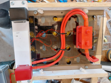
Yay, t-class fuse arrived, but the fuse-holder is so large, had to switch places, so ended up on top, while still being able to access the cell terminals.

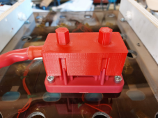
Didn't have a cover, so ended up 3d-printing one.

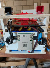
Put the BMS on the front.

Only thing I missed, was that the bar with battery main positive and negative is over the first row of cell terminals, ah well, in case I need to check torque, I can unscrew the complete bar and move it out of the way.

Very happy with the results, thanks to tips from you all.

1660502220529.png

1660502264745.png

1660502282189.png
 
That's a lot of juice!
The lexan is hard to drill round holes in, eh?? ;)

It's even harder to drill a square hole!
aghast.gif


(I have tools for my drill press that allow me to "drill" square holes. But I've only used that in wood.)
 
Acrylic/plexiglass is pretty easy to mill, more like wood, but you have to go slow to avoid heat buildup which makes the shavings melt.

Lexan/polycarbonate is really tough, think about five times stronger than acrylic. It's much more difficult to cut and mill, and heat is a real problem.

I ruined a hole-saw bit drilling mine, and had to do a lot of hand work cutting out the melted material around the lip of the hole. It looks pretty good from about 5', but close up it's not a clean cut.

The good news is it doesn't crack around fasteners as easily as acrylic. Still, buttonhead fasteners are recommended over counter-sunk for just this reason.

OTOH, Starboard/hdpe board cuts and drills like butter!

 
That's a lot of juice!
The lexan is hard to drill round holes in, eh?? ;)
280Ah, 24v ?

I used a hole saw for metal, no problem getting through it, but yes, the the heat slightly melted the edges. Didn't want to bother with trying to cool it or anything.

Tightened the threaded rods until I could no longer move the cells by hand, 'quite' snug. Still don't know at what point you start crushing them though, but at the top and sides of the cells, you can see there's still some room between each cell.

The battery is now live in the spot where it has to be.
 
Righto, I forgot to use the conductive paste on the BMS connections and fuse and so on, only used it on the cell terminals. So, took the thing apart, re-routed balance cables and made a protective cover for the BMS.

1660829265368.png

1660829305948.png

1660829322003.png

I'm done ;)
 
Acrylic/plexiglass is pretty easy to mill, more like wood, but you have to go slow to avoid heat buildup which makes the shavings melt.

Lexan/polycarbonate is really tough, think about five times stronger than acrylic. It's much more difficult to cut and mill, and heat is a real problem.

I ruined a hole-saw bit drilling mine, and had to do a lot of hand work cutting out the melted material around the lip of the hole. It looks pretty good from about 5', but close up it's not a clean cut.

The good news is it doesn't crack around fasteners as easily as acrylic. Still, buttonhead fasteners are recommended over counter-sunk for just this reason.

OTOH, Starboard/hdpe board cuts and drills like butter!

Chris would starboard be next step up from plexiglass for strength?
 
Back
Top