You are using an out of date browser. It may not display this or other websites correctly.
You should upgrade or use an alternative browser.
You should upgrade or use an alternative browser.
My DIY 14.3kwh EVE Battery Box Build
- Thread starter Struc
- Start date
Struc
Collecting Parts!
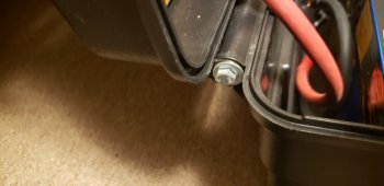
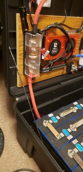
The lid was never meant to have weight attached to it and the hinge system for this box was very weak, so a couple of 1/4"-20 bolts and a nylock nut through a drilled hole in the corners worked great. Also added a restraint wire so it could only open so far. It's a stainless braided wire that I wrapped in electrical tape.


Struc
Collecting Parts!
Struc
Collecting Parts!
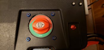
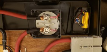
So, the battery is pretty much done now. I still need to clean up the BMS voltage sensing leads and put some spiral wrap around them, and label all the leads for when I move this and build it in its final destination. But I'm very happy with how everything turned out. Now to duplicate it with my 2nd set of cells...
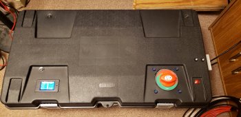
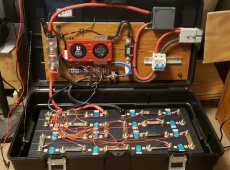


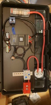
That directional MCB is no good as it is wired. It will only protect for internal faults and will burn out if you trip it whilst the battery is on load or for an external fault. To make it bi-directional, you need to wire one of the legs ( + or - ) the wrong way through the MCB. That way at least 1 of the poles will break the arc.
Struc
Collecting Parts!
That directional MCB is no good as it is wired. It will only protect for internal faults and will burn out if you trip it whilst the battery is on load or for an external fault. To make it bi-directional, you need to wire one of the legs ( + or - ) the wrong way through the MCB. That way at least 1 of the poles will break the arc.
Thank you for the info! I am going to have external protection on the inverters as well, so I may rethink it and come up with a different solution. I'm still betting the BMS will shut down long before I trip the breaker.
Struc
Collecting Parts!
Struc
Collecting Parts!
constantspeed
New Member
- Joined
- Jun 2, 2022
- Messages
- 61
I enjoy following your build process and progress, so thank you for sharing. After building a smaller version for my RV, I too do not understand your rationale for the placement of the MCB, or intended function? The T-class fuse ahead of your battery disconnect is your main protection and cutoff. The BMS also serves to hopefully not let things get too out of hand. The DC MCB is something normally used as a disconnect for the solar PV input, and seems unnecessary as configured.Thank you for the info! I am going to have external protection on the inverters as well, so I may rethink it and come up with a different solution. I'm still betting the BMS will shut down long before I trip the breaker.
Struc
Collecting Parts!
I don't disagree with you. But in my configuration, the Class T is ONLY there for a direct short really. A real major "oops" moment - and the Class T has the AIC rating to take care of it. They are far too expensive to be there for the primary overcurrent protection. Thus, they are sized large (400A). I don't want them to blow ever, but if they do, I'll be very happy I spent the money on them.I enjoy following your build process and progress, so thank you for sharing. After building a smaller version for my RV, I too do not understand your rationale for the placement of the MCB, or intended function? The T-class fuse ahead of your battery disconnect is your main protection and cutoff. The BMS also serves to hopefully not let things get too out of hand. The DC MCB is something normally used as a disconnect for the solar PV input, and seems unnecessary as configured.
I'm personally very hyper aware of the incredible amount of energy that is contained in one of these boxes, and I'm overcompensating by putting in more protection than needed. Class T, Circuit Breakers, Cut off switch, Anderson Connectors. If something screws up, I have lots of protection. Single points of failure and single points of protection are not in my nature.
constantspeed
New Member
- Joined
- Jun 2, 2022
- Messages
- 61
Nothing wrong with that, having multiple points of protection. It certainly doesn't hurt anything. CheersI don't disagree with you. But in my configuration, the Class T is ONLY there for a direct short really. A real major "oops" moment - and the Class T has the AIC rating to take care of it. They are far too expensive to be there for the primary overcurrent protection. Thus, they are sized large (400A). I don't want them to blow ever, but if they do, I'll be very happy I spent the money on them.
I'm personally very hyper aware of the incredible amount of energy that is contained in one of these boxes, and I'm overcompensating by putting in more protection than needed. Class T, Circuit Breakers, Cut off switch, Anderson Connectors. If something screws up, I have lots of protection. Single points of failure and single points of protection are not in my nature.
Struc
Collecting Parts!
is the dual MCB necessary on both the (-) and (+) ? just curious, my general take is to minimize the number of junctions/connections. Also, does the BMS have temperature sensing ? thank you for sharing your build
Not necessary. See Post #30.
post #30 concepts are well taken, but unless the usage of double pole on the DC is to increase the breaker combined trip point, there are an extra 2x mating contacts increasing total resistance. It's really a very minor point. Is there a temperature concern with the modules packed next to each other ?
Struc
Collecting Parts!
Not really. There should never be any heat build up there under normal conditions. The dual breaker allows another way to remove both poles of the battery from the system (Anderson connector being the other). I had a 2 pole breaker on the v1 battery, but was told I would need to run one of the poles the opposite way through it to make it work correctly. Solution was to use 2 1-pole breakers together.post #30 concepts are well taken, but unless the usage of double pole on the DC is to increase the breaker combined trip point, there are an extra 2x mating contacts increasing total resistance. It's really a very minor point. Is there a temperature concern with the modules packed next to each other ?
Cheap 4-life
My body is 2.63 trillion volts, .07v per cell
Do you remember which size wire lug was needed to fit both of the BMS wires into?
Struc
Collecting Parts!
Do you remember which size wire lug was needed to fit both of the BMS wires into?
4AWG
Cheap 4-life
My body is 2.63 trillion volts, .07v per cell
That’s for the jk?
Struc
Collecting Parts!
CorrectThat’s for the jk?
Similar threads
- Replies
- 45
- Views
- 2K
- Replies
- 5
- Views
- 172
- Replies
- 1
- Views
- 160


