


Steve_S
Offgrid Cabineer, N.E. Ontario, Canada
Links for products, many of which I use but some I have come across which may be helpful to anyone looking for specific bits.
Suggested Switch: https://www.bluesea.com/products/category/11/41/e-Series
Suggested Terminal Fuse for packs: https://baymarinesupply.com/blue-sea-mrbf-fuse-block.html
Bus Bar with cover: https://baymarinesupply.com/busbars-4-stud-250a.html
BMS "Chargery" with balancer : http://chargery.com/balancer.asp
Serial RS232/485 to Ethernet Converters (some with Modbus, CanBus available too)
Allows interfacing RS232/485 signals from devices by a PC, RaspberryP or other.
 shop.usriot.com
Battery Monitor with Hall Sensor:
 with Shunt (several versions available):
 PC Connectable with RS485 +
Suggested Switch: https://www.bluesea.com/products/category/11/41/e-Series
Suggested Terminal Fuse for packs: https://baymarinesupply.com/blue-sea-mrbf-fuse-block.html
Bus Bar with cover: https://baymarinesupply.com/busbars-4-stud-250a.html
BMS "Chargery" with balancer : http://chargery.com/balancer.asp
Serial RS232/485 to Ethernet Converters (some with Modbus, CanBus available too)
Allows interfacing RS232/485 signals from devices by a PC, RaspberryP or other.
Serial Ethernet Converter
shop.usriot.com
Battery Monitor with Hall Sensor:
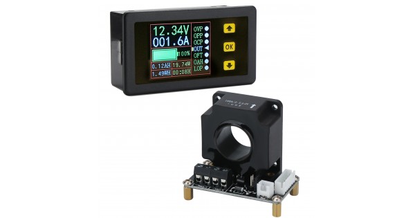
Digital Tester DC 10~90 V/100A Multifunction Voltage/Current/Capacity/Power/Coulometry/Time Display Panel Meter Monitor Meter
It is a Multifunction Tester/Panel Meter, Current Measurement Range: 0~100 A, Voltage Measurement Range: 10~90 V, It Can measure DC Voltage, Current, Power, Charge and discharge Capacity, time, and other Physical Quantities, Suitable for use in electrical work process parameters voltage, current
www.droking.com
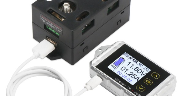
DC Voltmeter Ammeter Panel, Multimeter DC0~100V 200A Digital Meter Wireless Temperature Current Volt KWh Watt Meter Battery coulometer Capacity Power tester
Product Introduction: VAT series is a multi-function meter based on 2.4G wireless data transmission technology. It can measure parameters such as voltage, current, power, charge and discharge capacity, watt-hour, time, and temperature and with over-current protection, under-voltage protection,
www.droking.com
Last edited:
