diy solar

diy solar

My experimental 1.3Kw urban chimera

WoodsieLord

New Member
Joined
Oct 4, 2019
Messages
145
Location
Buenos Aires, Argentina (230V monophasic, 50Hz)
00a.jpg00b.jpg
It all started around 2018. Just like Homer Simpson building the circus tent with puree while dining it struck me: I've always wanted get into solar, why wait? "I'm already grown up, I have a job and I definitely want to" I told myself. So after coming back from vacation, around march 2019 I bought 4x 340w mono panels and a PWM charge controller...
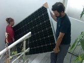
It just happens that I live in Buenos Aires city. More precisely on the 9th (and topmost) step, and the elevator stops at the 8th step. I had to think a safe way to put the panels on the roof while being able to fit everything inside the modest elevator.
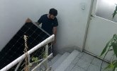
a00.jpga01.jpg

Once I got the panels, I stacked them by the bed where I had to look at them each day for almost a year.
a02.jpg
(the smiley thing was a gift for my son ?. Also, I'm not a tidy person. I could say 'Our wiring jobs speak for our tidiness')

Long story extremely short: First solar project. I planned the whole thing around an online UPS I own that I wanted to use as the inverter. No way to monitor State of charge, generation or consumption since I lack the accessory to do so. So I experimented with IoT to try to get data in DIY Style. This is by no means a professional project and I did it to learn. The final goal was to add some kind of intelligence that would read this data and command a relay module to enable or disable AC input from the power company to the UPS in a way that would take benefit from the sun while using my small battery bank as a mere "buffer". So you could say this kind of looks like a dumbed-down grid tie. That is, until I can afford a decent battery bank (appropietly sized).


Reading Volts, Amps and Watts with IoT devices..

I will try to share with you how I managed to read analog information (battery voltage, amps & watts both generated and consumed ) for my solar project. Please take into consideration that I'm no electronic nor electric engineer. I happen to be in IT and I started messing around with Arduinos and Raspberries as a hobby not long ago.


DISCLAIMER:

I'm a messy coder. I usually grab examples from the internet and start modifying them to reach my goals. My resulting code is known to cause nausea, memory loss, deep excruciating pain when staring blank and recalling parts of code even after discontinuing exposure to code, lose of will to live, alcoholism and other afflictions. Read at your own risk!
Also, I have a tendency to comment some lines in a primitive English and some in Spanish. I don't know why I do this but I've been doing that for quite some time.


a. To read DC voltages I use an arduino since the Raspberry pi has no analog pins in its GPIO.
b. To read current I use a separate chip interfaced via I2C to the raspberry. Technically speaking, this chip could also be integrated to the arduino using I2C but since most code examples available happen to be written in python, I chose to connect it to the RPI.
c. Battery State of Charge. If I know how much power comes and goes, I should be able to tell my battery SoC, right? Well.. it's not that easy.


a. Reading Voltages using an Arduino.

Arduinos feature analog pins and an integrated 10 bits analog to digital converter. In other words, some of these pins can be used to read voltages from zero up to "about 5V". This reading is interpreted as a 10 bit number that goes from 0 to 1024. In case of Arduinos, they will assign 1024 to voltages equal to the "VCC" (usually 5V).

If you power your arduino with 4.98V, then the analog pins will throw 1024 when the voltage detected is 4.98V. If you power your arduino with 5.08V, then 5V on the analog pin would be detected as ~ 1008 (since 1024 would be 5.08V).

You don't need to be a genius to understand that VCC can compromise the accuracy of those readings. In my case, I wanted the results to be consistent and I was willing to accept somewhat inaccurate values.


So! Most solar systems that we are used to read in this forum either work with 48V, 24V or 12V. So, reading up to 5V is pretty much useless. The solution is to use a voltage divider which will drop voltages to a desirable range, proportionally.
There are lot of examples and online calculators that I used to determine which resistors I needed and how to build the voltage divider. An engineer might get angry that I put the thing together just following recipes from the internet instead of understanding the underlaying maths, but remember that I started this as an experiment to learn.

useful link: https://circuitdigest.com/calculators/voltage-divider-calculator

Continuing... if 1024 is "VCC", then the Analog reading equals the approximate voltage produced by the voltage divider. With a simple conversion (considering the chosen resistors) we can arrive at an approximation of the actual voltage.

b00.jpgb00-1.jpg

At this point I had a working prototype that I tested with some replaced 12V SLA batteries from an UPS. I've tried many combinations and voltages and compared them with my multimeter. The accuracy shifted when I stopped using the arduino directly to my notebook and started interfacing it with the Rpi (probably because of the VCC). I was happy: after averaging some values, I send the result to the Raspberry through serial (Connected via USB) and I could read the voltage with simple python code.
b01.jpgb02.jpg

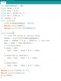
very early version of my arduino code.
C:
int analogInput = A0;
float vout = 0.0;
float vin = 0.0;
float R1 = 5100.0; // 
float R2 = 251.0; //
int value = 0;
float a1 = 0.0;
float a2 = 0.0;
float a3 = 0.0;
float a4 = 0.0;
float a5 = 0.0;
float a6 = 0.0;
float suma = 0;
int contador = 0;
void setup(){
   pinMode(analogInput, INPUT);
   Serial.begin(9600);
   // Serial.print("DC VOLTMETER");
}
void loop(){
   // read the value at analog input
   value = analogRead(analogInput);
   vout = (value * 5.0) / 1024.0; // see text
   vin = vout / (R2/(R1+R2));
   // Correcciónes !
   if(vin < 28){
      vin = vin - (vin * 6 / 100);
   }
   if(vin>=28 && vin<53){
      vin = vin - (vin * 6 / 100);
   }
   if(vin>=53){
      vin = vin - (vin * 6 / 100);
   }
   if(contador == 0){
      a1 = vin;
   }
   if(contador == 1){
      a2 = vin;
   }
   if(contador == 2){
      a3 = vin;
   }
   if(contador == 3){
      a4 = vin;
   }
   if(contador == 4){
      a5 = vin;
   }
   if(contador == 5){
      a6 = vin;
   }

  
   if(contador == 6){
      suma = a1+a2+a3+a4+a5+a6;
      vin = suma/6;
      Serial.println(vin,2);
      contador = 0;
   } else {
      contador++;
   }
   delay(300);
}

(I'll continue with more posts. Feel absolutely FREE to correct me. I'm no expert and my English is not that good either!)
 
b. Reading Currents with the Raspberry Pi.

When I got the voltage divider working, I wondered if I could read the voltage drop from a Shunt resistor. Well, yes and no. Typical shunts will produce a 0.075V drop when it's maximum capacity is reached (this means, a 50A shunt will show a 0.075V drop when 50A are being drawn). The resolution available (arduino) was impractical for this application.

Thankfully Craig suggested in a thread that I could use one of the INA chips and replace the integrated shunts with my own. The INA chips are the INA219 and INA226. Where I live I was able to get the smaller version only but I was able to get it to work with my 50A shunts. I just had to fry almost 8 of them until I got them to work. Darn it..!


These chips are interfaced to IoT devices via the I2C protocol. The I2C ... I have an unstable relationship with it. I love it when it works and I hate it and curse it soo much when it doesn't!

- My tips or advice is that i2c is very sensitive to interference and bad connections. Most of the time, it was plainly my fault that they didn't work. My soldering skills are decent for a hobbist And appaling for an electronics technician. I usually use too much flux or too little and these things are tiny!. Be patient. (The next ones are not scientiffically proven to work but are recommended) Do NOT watch i2cdetect indefinitely as it will interfere sooner or later with the chips. Do not cross under a ladder as it yields bad luck (I do it all the time).

Back to the INA chips:
Those chips are meant to be used up to 20ish volts and two or three Amps. They are considered "High Side" and if I got it right, you're supposed to connect the tiny shunt in the POSITIVE side. They use the Ground and Shunt voltage difference to get the system voltage and be able to calculate power units.
The way I've got it working is by ignoring the voltage detection from the INAs and placing it in the NEGATIVE side instead. So, I use the INA chips just to get the Current readings alone. Then I multiply these readings by the voltage to get power units.

Lately I'm using two shunts, one INA chip each. The second chip needs a solder lump between two contacts to switch its I2C Address so that they will not collide. Althoug at first I tried using only one.


I tried two libraries but I settled on this one:

The full code consists of many scripts that run between TWO raspberrys and they're way too long (including an i2c 20x4 LCD display refreshing status info, a 4 channel Relay board that I also use to... water some plants ("could you spare a Raspberry for the infirm-country-currency ?" shingling an empty can, emmiting coin sounds while I maintain eye contact with watery eyes. Just kidding. Although I would like to separate things in the future).


So I will proceed to share what I think are the key elements. But first I must address a few obstacles and how I sorted them. In part, so you know if you will have to face them too, and the latter so you can improve my unorthodox solutions.

1st. I needed TWO shunt readings: What I first did is kind of shameful but I basically edited the library (ina219) and duplicated the desired functions. Later I realized that I was able to create two separate "handles" by simply adding the address parameter.

2nd. It is HARD to understand/read a PWM cycle. This part forced me to read quite a bit and I "solved" this with a helping hand from Craig. When I first started testing with a single shunt, I've used a 12 volt gel battery and a cheap interactive UPS (not mine) with a ressistive load (45W soldering iron). I was able to get somewhat reliable results while on Battery mode, but the standard deviation while connected to AC (charging) was ludicrous.
I concluded that the charging mode used some kind of PWM cycle (like switching power supplies do) and I got good or wrong values depending on whether the reading "landed" on a HIGH or LOW part of the PWM cycle.
The Solution was simple (averaging many readings) but I didn't get it entirely on my own. Craig had already faced this in the past and was able to achieve consistent values by averaging 128 samples separated by 30 milliseconds each.

So, here are the interesting parts of my python3 code:
Python:
from ina219 import INA219
from ina219 import DeviceRangeError
..
# Time to wait between INA's shunt voltage readings.
tiempo_interlectura = 0.03    # Special thanks to Craig for this great expermiental finding!

# Amount of readings to get an average.
cantidad_lecturas = 128

# "Sentido" allows the possibility to reverse the direction of the measurements. If batt is discharging but this script reports "charging", this is the var to invert it.
sentido = -1 # (sentido 1 o -1, para invertir)
sentido2 = -1 # (sentido 1 o -1, para invertir)

# Shunt Ohms. Mine is 0.0015.
SHUNT_OHMS = 0.0015        # default para 50A 0.0015
SHUNT2_OHMS = 0.0015        # default para 50A 0.0015

# Max Amps that could be detected.
MAX_EXPECTED_AMPS = 50
MAX_EXPECTED_AMPS2 = 50
..

def read():
    ina = INA219(SHUNT_OHMS, MAX_EXPECTED_AMPS)
    ina.configure(shunt_adc=ina.ADC_128SAMP)

    try:
        valor = (ina.shunt_voltage())
        return valor*sentido
    except DeviceRangeError as e:
        # Current out of device range with specified shunt resistor
        print(e)
        return 0

def read2():
    ina2 = INA219(SHUNT2_OHMS, MAX_EXPECTED_AMPS2, address=0x41)
    ina2.configure(shunt_adc=ina2.ADC_128SAMP)

    try:
        valor = (ina2.shunt_voltage())
        return valor*sentido
    except DeviceRangeError as e:
        # Current out of device range with specified shunt resistor
        print(e)
        return 0

..
# I proceed with the INA chip. I will take the samples.
a = cantidad_lecturas
total = 0.00
total2 = 0.00
while(a>0):
    result = read()
    total = total + result
    
    result2 = read2()
    total2 = total2 + result2
    
    a = a - 1
    time.sleep(tiempo_interlectura)

result = total / cantidad_lecturas
amps = result * MAX_EXPECTED_AMPS / 75

result2 = total2 / cantidad_lecturas
amps2 = result2 * MAX_EXPECTED_AMPS2 / 75


This basic test allows me to get a watt rating (don't know if that's a good name or word for it). The values represent how many Watt·Hours would "transit" the shunt if conditions were to keep absolutely constant for a whole hour.

(continues...)
 
Building the mounts and placing the panels
c10.jpgc11.jpgc11-1.jpgc12.jpgc13.jpgc14.jpg
c15.jpg
(Unrelated note: Yesterday was Curfew Day No#120. Four months have passed. Yesterday, our Government announced that from next week onward Hair stylists and such will be able to Open their businesses. Go figure what my hair had become! Thankfully I had a home cut a few weeks ago. )

(still continues...)
 
c. Battery State of charge.

With this, I'm able to obtain "instantaneous" current readings. I publish these fairly inaccurate results via SNMP so another two raspberries can show via small LCDs. One is in the small "room" where the solar equipment is, the other is right above my TV in the living room.
d04.jpgf00.jpg

[...]I'm not a tidy person. I could say 'Our wiring jobs speak for our tidiness'
Early stages of the set up...
d00.jpgd02.jpg
d02-2.jpg


But this doesn't end here. I wanted to implement a way to have a State of charge for my batteries. I made many mistakes here but mistakes are opportunities to learn.

The first mistake was ignoring the Coulombic Efficiency and the Peukert Effect. I thought about my batteries as a Water tank (I remove 10 liters, then I add 10 liters, so the tank must be exactly in the original state). Batteries won't exactly behave like liquid. Depending on the chemistry we might have to spend more energy to fill it than the energy it will be able to provide. This would be the coulombic efficiency. And, if we have a 1000L tank and we drain 200L very slowly or if we drain them extremely fast (like a toilet turbo discharge!) we know for sure that we have 800L of liquid remaining either case. Yet again, Batteries do not behave like this and the capacity is dependent on the rate at which we pull or push energy from them.
I understood these concepts thanks to this video from Will:


For the sake of experimenting I decided to ignore this and proceed to see what kind of results I could achieve.
Back to the INA chips, they report "instantaneous" measurements. For example, let's pretend that right now they state that the house is draining 300W from the battery bank, this translates to "if an hour would go by while all readings stay the same, then the bank capacity would decrease 300Wh" (again, ignoring CE and Peukert for simplicity).
The easiest way I found to translate this into code was to take a number of measurements (6 If I recall) average them while keeping track of the time spent from start to finish. I played around with this until I got the whole process to take around 30~40 seconds. So, if the read number indicates how many W·h would change if conditions would stay the same for one hour, then I can calculate the proportional W·h that would change in the smaller 30~40 seconds interval:

Python:
# wattsAVR are hourly based. If 1 hour means [wattsAVR], then [timeWindow] means [timeWindow*wattsAVR/3600seconds]
effectiveWatts = timeWindow*wattsAVR/3600
effectivePV = timeWindow*wattsPV/3600


Remember that my system works with an UPS that will charge the batteries from the grid once the sun won't supply enough power to cover the load at the time.
e02.jpg
(ignore the Coulombig efficiency sensor in the image. The value is never updated)

After testing for months I was pretty familiarized with the UPS charging (voltage and watts) curves to identify when the battery was beginning to get full and once it was floating. As the Coulombic efficiency is lower than 100%, it happened many times that the primitive "State of Charge" reported 100% while the UPS was still charging it at the usual "full" rate. I used this to modify my scripts temporarily to calculate the amount of watts drained during the night (in my case this is the lowest and most stable power consumption, around 200W) vs the amount of watts charged later on until the "known parameters" were back to normal (that means, until the bank voltage and watts IN were slightly near float)
I did three tests like this and arrived at 0.9191. That means that for every 0.9191 watt·h drained from the bank, I had to spend 1 watt·h to recharge it.

So my coulombic efficiency seems to be ~ 0.92 (92%). I think that number is more or less what could be expected from a gel lead acid battery. But I know I made many assumptions to be able to claim that this number is trustworthy. So I still consider it to be part of my experiment.

Since I calculated that value, I'm using it as a correction to my SoC calculation and I have to say that the synchronization (between reaching 100% and observing voltages and power to get near floating values) got quite better. From many hours to one or less.

(just a tiny bit more to come)
 
I want to introduce you to my selector switch.
d05.jpg
(selector switch says 'hi')

The switch as tree positions. I use it to:

1. force GRID (keeping the UPS permanently hooked up to grid and interrupting the connection from the panel arrays to the SCC).
2. force OFFGRID (keeping the UPS out of the grid and enabling the connection from the arrays to the SCC).
3. Use an "Automatic" selection.

The "Automatic" thing, is my most terrifying chimera yet. Simply put, the script checks for solar feasibility on time intervals during daytime. The feasibility check consists of switching to offgrid (interrupting the grid) and check if the battery is draining or not. If it's not draining, I keep it like that and it will keep checking every minute. If a cloud passes by, the system will switch back to grid and wait (currently half an hour) before attempting to switch back to offgrid. Super inefficient. But I used it like this for two months.
It performed acceptable until last month when I decided to replace my PWM SCC with an MPPT.

g00.jpg

Now, the issue I'm facing is that the feasibility tests will result in false negatives almost everytime, since the MPPT SCC takes a while longer to produce a decent output. I also have an issue with it that sometimes I have to completely shut it down and restart it to ramp up power to the expected values.

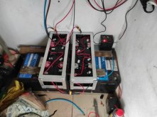
After tiding. Replacing wires with better ones and removing the older PWM SCC.
g01.jpg

THE END. (for now)
 
a. Reading Voltages using an Arduino.
Arduinos feature analog pins and an integrated 10 bits analog to digital converter. In other words, some of these pins can be used to read voltages from zero up to "about 5V". This reading is interpreted as a 10 bit number that goes from 0 to 1024. In case of Arduinos, they will assign 1024 to voltages equal to the "VCC" (usually 5V).

If you power your arduino with 4.98V, then the analog pins will throw 1024 when the voltage detected is 4.98V. If you power your arduino with 5.08V, then 5V on the analog pin would be detected as ~ 1008 (since 1024 would be 5.08V).

One comment: it is possible to read an INTERNAL REFERENCE VOLTAGE of 1.1 V in the Arduino. See https://www.arduino.cc/en/Reference.AnalogReference then your results become independent of variations of the Vcc. Here is another description that may be useful: http://www.skillbank.co.uk/arduino/measure.htm.
 
Yay! Been waiting to hear about this...at some point my batteries will be here and it'll be my turn in the frying pan...

...I have a tendency to comment...
So, not a professional coder then.... ;-)

..[use] a primitive English and some in Spanish. I don't know why I do this but I've been doing that for quite some time.
Some curses just sound better in a particular language. That you're picking the correct one shows an innate artistic ability and you shouldn't feel fettered by that.

... To read DC voltages...
As a measurement in an active circuit relating to SoC... does anyone know what it's really good for?
Good thing you're using a shunt!

... I use an arduino... since the Raspberry pi has no analog pins in its GPIO.
You might be interested in the Teensy, lots of pins and you can reuse the arduino code. Not sure why you're using two Pis and Arduino?

...c. Battery State of Charge. If I know how much power comes and goes, I should be able to tell my battery SoC, right? Well.. it's not that easy.
Voltage ≠ SoC, except after a quiescent period. But getting the watts in and out, accounting for inefficiencies in both directions should get you SoC.

... I put the thing together just following recipes from the internet instead of understanding the underlaying maths, but remember that I started this as an experiment to learn.
I smell magic smoke coming!

... The I2C ... I have an unstable relationship with it. I love it when it works and I hate it and curse it soo much when it doesn't!
Does the Arduino have pull-up resistors built in? Could using a lower frequency make it more stable?

... I concluded that the charging mode used some kind of PWM cycle (like switching power supplies do) and I got good or wrong values depending on whether the reading "landed" on a HIGH or LOW part of the PWM cycle.
Yikes! Kudos to @Craig!
 
Last edited:
I smell magic smoke coming!
Lots of magic smoke got away along the way. Now I'm left with their empty vessels. Their silence a reminder of the pain (in the b..) that was replacing them :ROFLMAO:


Not sure why you're using two Pis and Arduino?
Good question. The answer would be that the set up is outdated: The lower one has de INA chips to read the Shunts and the Arduino (battery bank voltage).
The upper one controls the Relay module, the LCD screen and the selector switch. These things could be added to the same Raspberry, True. Thing is that in an early approach I had both RPIs without common ground (different power sources) so that a second arduino could be used to read the Array voltage. I quickly disregarded this approach since the arduino would hang and its voltage divider kind of overheated. I think my resistors were too small for the job or the VOC was too high for them. It was useless even when it worked because the thinnest of sun touching the panels would yield a deceivingly 'good' voltage. There was a stage when I added an incandescent bulb that was turned ON when the array was not connected to the SCC. It was very messy and I chose to abandon that approach completely.

To address this, I'm currently thinking about building a tiny 'solar instrument' with a toy-sized panel to speculate when there is power. This would optimize the automatic selection feasibility test... what do you think?
 
Last edited:
This is great stuff! Thank you for sharing!
...[pics of cables all over the place driving my OCD crazy]...
Somebody needs a label maker! ;-)

...The first mistake was ignoring the Coulombic Efficiency and the Peukert Effect.
I've been wondering if I'd have to worry about the Peukert for LiFePO4, guess I'll find out.

...I thought about my batteries as a Water tank (I remove 10 liters, then I add 10 liters, so the tank must be exactly in the original state).
Nice analogy! Just add it's an "Open top" delivery pipe, ~8% evaporation occurs during transport. Your actual rate with the Alphas was 92%, awesome!

I wonder if Peukert could follow that analogy too... think of it as the pump has to apply more pressure to push the current out faster and there's a leak in the pipe such that at low pressure it's just a drip (20 hour rate) and high pressure it's a stream.
 
Last edited:
...To address this, I'm currently thinking about building a tiny 'solar instrument' with a toy-sized panel to speculate when there is power. This would optimize the automatic selection feasibility test... what do you think?...
Currently I scrape the solar irradience off a nearby weather underground station. Sometimes one or the other has clouds so you have to average the data. But... I was thinking the same thing... put it on top of an anemometer on the roof to both power the anemometer and provide an independent measurement.

Not as good as Pyranometer and as my panels get coated with pollen it'll get coated too so there's that problem. I'll probably keep the weather underground data and merge it in, although I have no idea if they're keeping the pollen wiped off theirs ;-)

I think Pyranometers are just a black metal plate the sun heat's up (cooler when covered by clouds) that's in a vacuum using a temperature sensor and algorithm. Possibly there's some middle ground to be explored between super expensive, cheap/accurate-enough, and not likely to get soiled or suffer from the environment.
 
View attachment 18427
View attachment 18428

I finally added the remaining two panels.
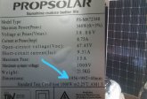
The original four are these:
View attachment 18429

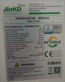
The newer ones are these:
View attachment 18430

Currently, I have them in 2s3p arrangement. I know my MPPT can handle up to 150V, so I think I could do 3s2p, but I don't know if that would make a benefit or not
The way your panels are placed, you risk to frequently have a part of the panel shaded. A soon as a panel has a row of cells shaded it loses 80% of its power.
You would have been better off by removing the two panels on the chimney side and placing the other ones in such a way that they are not shaded.
 
I was very limited on the disposition for the panels. I wanted the less intrusive approach to fix them in place while at the same time making it strong to survive winds.

Anyway, before I stared, I tried to follow the sun. I did this in april (I'm at the south hemisphere). I took some pictures
shade.jpeg
The Chimney never casts its shadow over the panels. The roof borders do, but I prefer the border protection from the wind.
The only thing I would love to do (but I won't for security reasons) is to tilt the panels to catch the early morning sun.

thanks and regards
 
...casts its shadow over the panels. The roof borders do, but I prefer the border protection from the wind.
That is what I meant. You ought to elevate the panels at the height of the roof borders, they will be protected from the wind as well.
By the way: the most frequent and worst wind damage does not occur from the push force of the direct wind, but from the pull force of the wake behind the wall front.

By the way, what do you think about moving this discussion to the new section:

Home Brew Solar Electronics

 
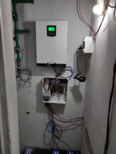
a tiny update on my chimera. I installed the all in one inverter I got ( mpp clone ). It exceeded my expectations being a clone on the cheap side.
screenshot.6875.jpg
(picture: installing the inverter, rearranging batteries, testing)


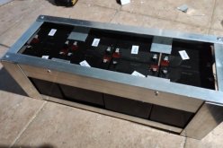
I got my hands on 5Ah SLA batteries. LOT of them, thankfully for free. I'm slowly making some aluminium enclosures arranging them in packs of 2s4p. I would like to build twelve of these packs.
screenshot.6876.jpg

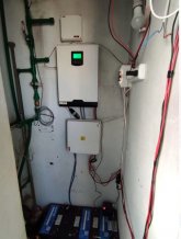
Cable management getting a little better
screenshot.6877.jpg
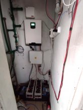
I know, I know. It's not over yet. But if you compare this to a few months ago...


Lately I connected two of the packs and they seem to work well. I'm guessing I will have lot of difficulties with balance by having so many small batteries in parallel. These batteries were pulled out (replaced) from 6000VA UPS which feature 20 batteries in series (240V DC). Apparently they perform decently.

screenshot.6878.jpgscreenshot.6879.jpg
 
Back
Top