diy solar

diy solar

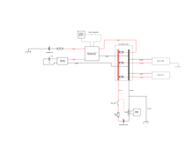
My first blueprint for 12V 400W camper setup. Anyone willing to check for mayor failures?

keeeenleee

New Member
Joined
Jan 5, 2022
Messages
11
Hi, im a off-grid virgin and after 2weeks of research, I prepared a blueprint. It's 12V camper system with:
  • 200Ah LFP battery
  • 400W solar panels
  • 1200W inverter

Before I make a purchase of all components, I would like to get some feedback if something is wrong or need some optimisation.

Especially I would like some approval about grounding, fuse sizes and corresponding wire sizing.

Current situation is that I already have 1200W pure sine inverter and 400W of solar panels, so this are the only two things that I don't want to change, the rest of the diagram is open for discussion.

And at the end, thanks anyone here that help creating such nice community ?
blueprint.png
 
Seems like a reasonable design... One thing to note, make sure to factor in cable lengths when determining cable gauges and make sure you add gauge appropriately for the lengths required in order to have minimal voltage drops.

I'm not really seeing any real red flags on the diagram (but then-again, it is afternoon and all)... I didn't check on all the fuse sizes, just remember to size fuses accordingly to protect the wires.

Fuse locations are important in the sense that if a wire shears through the insulation say, you want the fuse to be mounted as close to the power source as possible, to protect as much of the wire as possible (so a pinched wire say, shorted out to ground, the fuse would likely be on the correct side of it, so as much of the wire is protected as possible).

Did you have any specific concerns about your grounding?
 
A 1200W inverter on a 12V system will be about 1200W / 12V / 0.85 = 120A. You could use 2AWG though 1AWG would be better. Combine that with a 150A fuse. Your diagram shows 2/0AWG for the inverter and 175A fuse. Both of those will work but are bigger than needed.

The 4/0AWG for your battery may be overkill. It depends on your max 12VDC loads. If you had a 100A of 21VDC loads while running the inverter at the full 1200W then that would be about 240A. Then 4/0AWG is a good choice but then the 200A fuse is too small for the loads.

The 2AWG you show for the 12V fuse box implies you plan on at least 100A of DC loads. If you plan on 100A of loads then the fuse should be 125A.

Make sure the battery shunt is at least 250A.

The 4AWG and 65A fuse for the Renogy DC-DC/MPPT seems like a mismatch. 4AWG would be used for 80A-100A of loads so a 65A fuse is rather small. If the output of the Renogy is 50A total then 6AWG is fine and the 65A fuse would be a good match.

The max PV input voltage of those Renogy DC-DC/MPPT is really small so you probably have to wire your panels all in parallel. You don't say what panels you have. Is it 4 100W or 2 200W or 1 400W?

Both wires from the panels would go to the MPPT. Your diagram shows the negative going to the bus bar. It should go to the MPPT.
 
Only thing I will add just to feel useful is a chassis ground for the inverter. I know it looks like it is chassis grounded already, but you will need a second ground wire from the inverter chassis ground lug (they all have them) to the chassis or just run it back to the distributor. Seems silly, but that's what I did and it seems to be approved.
 
Only thing I will add just to feel useful is a chassis ground for the inverter. I know it looks like it is chassis grounded already, but you will need a second ground wire from the inverter chassis ground lug (they all have them) to the chassis or just run it back to the distributor. Seems silly, but that's what I did and it seems to be approved.
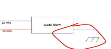
If I'm not mistaken, the diagram already shows additional chassis grounding for inverter. I used this symbol for grounding. Would you say it already ok?
Screenshot 2022-01-07 at 13.00.16.png
 
Seems like a reasonable design... One thing to note, make sure to factor in cable lengths when determining cable gauges and make sure you add gauge appropriately for the lengths required in order to have minimal voltage drops.

I'm not really seeing any real red flags on the diagram (but then-again, it is afternoon and all)... I didn't check on all the fuse sizes, just remember to size fuses accordingly to protect the wires.

Fuse locations are important in the sense that if a wire shears through the insulation say, you want the fuse to be mounted as close to the power source as possible, to protect as much of the wire as possible (so a pinched wire say, shorted out to ground, the fuse would likely be on the correct side of it, so as much of the wire is protected as possible).

Did you have any specific concerns about your grounding?
Aha I will position fuses directly to the positive of power sources. And the rest of them will be placed in a distributor that will be a few inches away from most of my components.

Regarding the grounding I just want to make sure if my thinking to ground (chassis) the central distributor makes all other components grounded?

And for inverter I will make additional grounding (im not sure why, but all inverters have this separate grounding pin that suggest direct connection to chassis.

Maybe someone knows why inverters have this, and why most other components have grounding via negative lead?
 
Maybe someone knows why inverters have this, and why most other components have grounding via negative lead?
Redundant safety. Another path to insure a fuse blows or an internal fault can dissipate.

The weird thing (to me) is most of the commodity units case/chassis ground have a stud size that looks like a 10ga wire was intended. In my head I’d want it much much bigger for DC. Size of the studs suggest they intended them for an AC application?!
 
Last edited:
Redundant safety. Another path to insure a fuse blows or an internal fault can dissipate.

The weird thing (to me) is most of the commodity units case/chassis ground have a stud size that looks like a 10ga wire was intended. In my head I’d want it much much bigger for DC. Size of the studs suggest they intended them for an AC application?!
Aha I noticed that for my inverter they suggest 12 ga wire. Im will put at leat 10ga or thicker.
 
A 1200W inverter on a 12V system will be about 1200W / 12V / 0.85 = 120A. You could use 2AWG though 1AWG would be better. Combine that with a 150A fuse. Your diagram shows 2/0AWG for the inverter and 175A fuse. Both of those will work but are bigger than needed.

The 4/0AWG for your battery may be overkill. It depends on your max 12VDC loads. If you had a 100A of 21VDC loads while running the inverter at the full 1200W then that would be about 240A. Then 4/0AWG is a good choice but then the 200A fuse is too small for the loads.

The 2AWG you show for the 12V fuse box implies you plan on at least 100A of DC loads. If you plan on 100A of loads then the fuse should be 125A.

Make sure the battery shunt is at least 250A.

The 4AWG and 65A fuse for the Renogy DC-DC/MPPT seems like a mismatch. 4AWG would be used for 80A-100A of loads so a 65A fuse is rather small. If the output of the Renogy is 50A total then 6AWG is fine and the 65A fuse would be a good match.

The max PV input voltage of those Renogy DC-DC/MPPT is really small so you probably have to wire your panels all in parallel. You don't say what panels you have. Is it 4 100W or 2 200W or 1 400W?

Both wires from the panels would go to the MPPT. Your diagram shows the negative going to the bus bar. It should go to the MPPT.
I went through all of your suggestions. It helps me further improve my wire size/fuse compatibility. And yeah, most probably I will not use 240amps of load.

One thing that just got to my mind. Im planning to use SOK 200Ah LFP battery. And it has only 100A of maximum discharge. Should I take this into account and pick smaller fuses (125amp instead of 200amp) to take into account battery's maximum discharge rating?
 
noticed that for my inverter they suggest 12 ga wire. Im will put at leat 10ga or thicker
Referring to the ‘earth?’ Or the 120VAC output?

For the 120VAC output 12ga is fine as that supports double the output amps of the inverter.
Should I take this into account and pick smaller fuses (125amp instead of 200amp) to take into account battery's maximum discharge rating?
The fuse is there to provide current protection for the cable. At max output the 12V input shouldn’t be over 100A. So a 125A fuse is appropriate for the right size cable.

For inverters and other high-amp devices I usually oversize the input cables.
I too use a 1200W inverter which I supplied with 2/0 cable but I fused as if it were 2AWG using a 125A fuse. While that is not necessary, it provides for possible future upgrades, adds a ridiculous overmargin of safety, and guarantees they will never become hot. That’s just my practice.

Summary. For big-amp devices I recommend that you fuse for whichever is lower: the wire/cable Amp Rating OR the max amps of the load.
…SOK 200Ah LFP battery. And it has only 100A of maximum discharge. Should I take this into account
The fuse needs to protect the cable regardless of the input potential.
 
Which panels? The Renogy DCC50 is rather limited in my opinion since it only allows 25V max input for the PV panels.

Also, it's only 25A PV and 25A from the alternator.

I'd prefer separate units. A decent MPPT allows higher voltage from the panels, allowing you to serie-wire multiple, or use cheaper panels
Also, if anything fails, you still have solar or alternator charger, with an all-in-one both are gone.
I bought an used camper that already has panels wired in parallel. I will have this van for 2-3 years and then build a newer one with better units. So I understand your point, but for this build its reasonable to use this DCC50. I also like that this unit support trickle charging for the car battery with solar energy.

On my next camper I want to connect the panels in series, and at that point I will use separate B2B and MPPT.
 
I’m told that a class T fuse is required/appropriate for lifepo4 for you it’s ability to interrupt dc current flow. (AIC)?
 
I’m told that a class T fuse is required/appropriate for lifepo4 for you it’s ability to interrupt dc current flow. (AIC)?
Ok, good to know. I checked what Will wrote on his page about fuses:
The ANL fuse above works great for most 12V systems...

But if you are building a large 48V lithium based solar power system, the arc that it can create in a fault can be massive! So large in fact, that the ANL fuse above will not save your system if a fault were to occur.

In this instance, you will need a T Class fuse. This fuse can work on any size battery bank, and will protect your system better than anything else around.

These are more expensive than an ANL fuse, but if you are using a 48V battery bank, these are required!

So for 12V I think I can go with mega fuse or circuit breaker.
 
Mega fuse: Probably ok, unless you have a huge bank (multiple cells in series). Wires will probably assure the short circuit current is within specs (interrupting rate)

circuit breaker: If you really need to, get a decent one (Blue Sea Systems or so). Most people use the cheap black/red ones which are crap and generally causes issues.
(heating up massivly, random tripping, way below their rated current, massive voltage drop causing inverters to shutdown on low voltage alarms and so on)

Personally I never use it. A fuse should not trigger frequently, only on a rare occasion, and is supposed to never trip. If it needs frequent replacement and trips, your design is crap. Using a resettable breaker is not fixing the root cause
 
One thing that just got to my mind. Im planning to use SOK 200Ah LFP battery. And it has only 100A of maximum discharge. Should I take this into account and pick smaller fuses (125amp instead of 200amp) to take into account battery's maximum discharge rating?
Since your total loads can be well over 100A at times, you may be better off getting 2 SOK 12V 100Ah batteries and putting them in parallel. This will give you 200A max continuous discharge.
 
Back
Top