My first solar system was fired up today! I am sharing pictures/details so the more experienced can critique as I don't know what I don't know.
Component list:
- 12 volt starter battery; probably about 70 to 80 amp hour (I know this should be upgraded, but it is what I had kicking around)
- 315 Watt Longi Solar Panel (LR6-60HPH): VOC = 40.6 volts; Isc = 9.94 amps
- Victron Phoenix 12/375 inverter: 300 W continuous; 700 W peak; zero load is 5.6 W
- Victron Smart Solar 100/20 MPPT: 20 A and 100 VOC; nominal PV power is 290 W on 12Volt set-up. I'm slightly over-paneled, but well under the VOC rating and according to Victron, that is OK
- 10 x 15 x 1/4" galvanized grounding plate
- 6 gauge grounding wire to bus bar
- all black insulated wire is 10 gauge. I had a bunch of black wire to use up. If it's wrapped with red electrical tape at the terminal, it is positive.
- green wire is 10 gauge and used for grounding.
- Powerfist 30 amp stud type automatic resettable circuit breaker (wrapped in red tape in picture)
- 2 Tocas Thermal circuit breakers rated for 30 amps
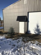
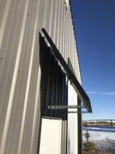
Panel is mounted at around 30 degrees from vertical. Ideal is 24 degrees for December and 54 for the summer. It will primarily be used in the winter, so that is why the angle favors winter. It is mounted with 4 bolts as per Longi's recommendation for heavy loads. 60 MPH wind gusts are fairly common in this area. I hope this is sufficient.
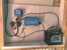
I used a cement fiber board over top of 3/4" plywood as a backer for mounting the electrical components to give myself a bit of "fire insurance".
In all cases, I've used the largest gauge wire that the devices can accommodate. The only exception to this is the wire connected to the inverter. The inverter can accommodate 8 gauge, but I used 10 gauge. The user manual for the inverter indicates that 10 gauge is acceptable if the length of the wire is < 1.5 m (4.9') which is true in my installation.
The wiring is a bit of a mess, but I managed to keep the runs relatively short and I think I avoided putting much stress on wires at connection points. If you are trying to trace the wiring, the wires from PV are on the far left of the diagram. The positive goes to the Tocas circuit breaker and then the MPPT. I'm mainly using the Tocas circuit breakers for switches.
The inverter is remotely switched on and off by the charge controller (yellow wire). The load circuit is programmed to turn on when the battery voltage is over 13.75 volts, stay on for 1 hour, and turn off if the battery voltage drops below 12.5 volts; thus the inverter will follow the same. I know these are odd voltages to use. I've got a tiny load on the inverter (<10 watts), and it only needs to come on once a day for an hour. Thus, I figure I will try and get it to only use the battery when there is sun out to replenish it. This battery isn't appropriate for deep cycles and it is an unheated shed so I want to keep voltage high enough to prevent freezing. If/when I get some lights or need to use power tools, I'm going to have to change the programming. Fortunately, the Bluetooth connection to the MPPT makes this relatively easy to do.
I installed the system and put the largest load I could put on the inverter without it tripping off. I ran it for a number of minutes and couldn't feel any heating in the wires. I've double checked all connections and things are tight.
Any comments/concerns? Have I missed anything? It's powered down until I get some feedback. Thank you in advance!
Component list:
- 12 volt starter battery; probably about 70 to 80 amp hour (I know this should be upgraded, but it is what I had kicking around)
- 315 Watt Longi Solar Panel (LR6-60HPH): VOC = 40.6 volts; Isc = 9.94 amps
- Victron Phoenix 12/375 inverter: 300 W continuous; 700 W peak; zero load is 5.6 W
- Victron Smart Solar 100/20 MPPT: 20 A and 100 VOC; nominal PV power is 290 W on 12Volt set-up. I'm slightly over-paneled, but well under the VOC rating and according to Victron, that is OK
- 10 x 15 x 1/4" galvanized grounding plate
- 6 gauge grounding wire to bus bar
- all black insulated wire is 10 gauge. I had a bunch of black wire to use up. If it's wrapped with red electrical tape at the terminal, it is positive.
- green wire is 10 gauge and used for grounding.
- Powerfist 30 amp stud type automatic resettable circuit breaker (wrapped in red tape in picture)
- 2 Tocas Thermal circuit breakers rated for 30 amps
Panel is mounted at around 30 degrees from vertical. Ideal is 24 degrees for December and 54 for the summer. It will primarily be used in the winter, so that is why the angle favors winter. It is mounted with 4 bolts as per Longi's recommendation for heavy loads. 60 MPH wind gusts are fairly common in this area. I hope this is sufficient.
I used a cement fiber board over top of 3/4" plywood as a backer for mounting the electrical components to give myself a bit of "fire insurance".
In all cases, I've used the largest gauge wire that the devices can accommodate. The only exception to this is the wire connected to the inverter. The inverter can accommodate 8 gauge, but I used 10 gauge. The user manual for the inverter indicates that 10 gauge is acceptable if the length of the wire is < 1.5 m (4.9') which is true in my installation.
The wiring is a bit of a mess, but I managed to keep the runs relatively short and I think I avoided putting much stress on wires at connection points. If you are trying to trace the wiring, the wires from PV are on the far left of the diagram. The positive goes to the Tocas circuit breaker and then the MPPT. I'm mainly using the Tocas circuit breakers for switches.
The inverter is remotely switched on and off by the charge controller (yellow wire). The load circuit is programmed to turn on when the battery voltage is over 13.75 volts, stay on for 1 hour, and turn off if the battery voltage drops below 12.5 volts; thus the inverter will follow the same. I know these are odd voltages to use. I've got a tiny load on the inverter (<10 watts), and it only needs to come on once a day for an hour. Thus, I figure I will try and get it to only use the battery when there is sun out to replenish it. This battery isn't appropriate for deep cycles and it is an unheated shed so I want to keep voltage high enough to prevent freezing. If/when I get some lights or need to use power tools, I'm going to have to change the programming. Fortunately, the Bluetooth connection to the MPPT makes this relatively easy to do.
I installed the system and put the largest load I could put on the inverter without it tripping off. I ran it for a number of minutes and couldn't feel any heating in the wires. I've double checked all connections and things are tight.
Any comments/concerns? Have I missed anything? It's powered down until I get some feedback. Thank you in advance!