diy solar

diy solar

My first off-grid system for review

TechnoTime

New Member
Joined
May 7, 2021
Messages
38
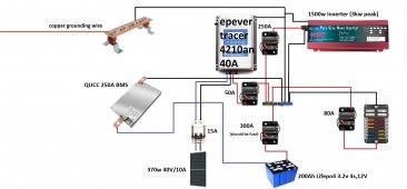
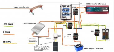
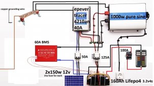
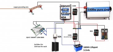
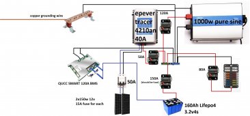
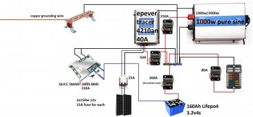
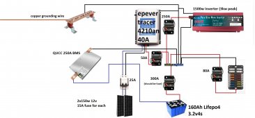
Hello everyone! I'm a total newbie, and this is what I've come up with after a week of research. It's for off grid sauna cabin.

I pretty much only need it for lights, which I plan to run on 12v DC from fuse box (adding some USB outlets for phone / laptop charging). Then I'll have couple of 230v AC sockets as well from my inverter, just in case.

What I'm mostly confused is:

1. Is my BMS big enough and is it OK to connect it the way I did in diagram?
2. Is fuse box connected properly.
3. Are my breakers in proper size?

Batteries gonna be DIY aliexpress cells. All system together is roughly 600 eur (730 usd), so quite cheap. We have proper winter here for a few months, so I'll add DIY automated battery heater, as the electricity box gonna be outside cabin. For those cells, it's written that charging temperature is from -10C, should I trust that or should I never let them charge below 0?

Thanks!
 

Attachments

  • test2.jpg
    test2.jpg
    344.3 KB · Views: 51
Last edited:
The BMS goes between the battery and everything else (except the OCP). Connect everything to your common bus bars. Then connect the negative common bus bar to the BMS.

Your 125 amp OCP (Over Current Protection) device goes between the positive post of the battery and the positive common bus bar. Dual pole isn't necessary. Most implementations are using a fuse, not a circuit breaker. A Class T fuse is the general recommendation. There are some circuit breakers that could be used in this position, but they are almost as expensive as a Class T fuse.

Your BMS probably is NOT big enough. The 1000 watt inverter often has a much higher surge wattage. However, if you know that you'll never pull more than 60 amps out of the battery that BMS might work. I say "might" because the Daly BMS is often derated by as much as 50% to get a real rating.

There should be a circuit breaker between the common bus bar and the inverter.

The 100 amp circuit breaker going to your DC distribution panel is probably too high. It depends on how many amps will be pulled through that device at any one time. In my case, 40 amps would appropriate.
 
Thanks a lot! Really appreciated!

This is the new improved diagram. I still put in breaker for OCP, is it really that big of a deal? Otherwise it should be okay now (except grounding maybe). I'm not sure how many amps my DC distribution panel gonna pull at max. It will be 10-15 LED 5-10w LED bulbs, then some USB charging at max (and 4x7w heating pads for battery if gets cold). Wiring might get somewhat long-ish, as cabin gonna be 2 floors with integrated wiring. That's why I put a larger breaker there.

1. Grounding - is it enough to just ground negative common bus bar, or should I also ground SCC and inverter seperately?
 

Attachments

  • diagram_with_grounding1.jpg
    diagram_with_grounding1.jpg
    216 KB · Views: 21
Anything that has a grounding screw, needs to be grounded.

The black line directly between the battery and the negative bus bar needs to go away. The BMS is the link between the battery and the negative bus bar.

There should be a 50 amp circuit breaker between the solar charge controller and the positive bus bar.
 
Thanks again! This should be the final version then.
 

Attachments

  • diagram_with_grounding2.jpg
    diagram_with_grounding2.jpg
    223 KB · Views: 13
Thanks again! This should be the final version then.

Ha! Famous last words. I stopped keeping track of versions of my diagram.
rolleyes.gif


The amp rating on your dual pole circuit breaker between the solar panels and the solar charge controller is probably too high. You didn't provide the specs on your panels or the configuration (2s, 2p, etc), so it's hard to say how high the voltage and amps will be. 1.25 times the max amp output of the panels is what you should side the circuit breaker to. Be very careful when purchasing circuit breakers. They MUST be DC rated.

All circuit breakers should be good quality from well known manufacturers. Bussman or Blue Sea Systems are what I used for the non-dual pole breakers.
 
Ha! Famous last words. I stopped keeping track of versions of my diagram.
rolleyes.gif

True, there likely gonna be 10 more versions before final "final" version. I didn't know a thing about solar (or electricity) a week ago, so it's been fun.

Panels gonna be connected in series. Specifications are: Rated power: 150 W, VOC: 20.3V, Short Circuit Current (Isc): 9.61A, Working current (IOP): 9.04A, Output Tolerance: 3%. Therefore gonna work out at 40V/20A circuit? I'll put 15A fuse for each panel already, so that 50A breaker just gonna work more as a switch, but can change it to 25A, no biggie.

I modified inverter to 1k/2kW (so I could run low wattage hair dryer) - can I get by with changing my inverter breaker to 250A and OCP to 300A? I guess not as I'd have to up my BMS as well.. Or maybe could get by as for 1000 continuous wats max output Amps is 134 according to this table I'm looking at. I could up BMS to 150A, costs 5 eur more.

About wires - I am thinking to put 50mm2/1 AWG cable from Battery positive to breaker, and from that breaker to common positive bus bar. Rest of the wiring with 35mm2/2 AWG cables (except PV cable from panels to SCC). Everything gonna be placed close. Is this okay ir should I go bigger / can go smaller somewhere?
 

Attachments

  • diagram_with_grounding2000inverter.jpg
    diagram_with_grounding2000inverter.jpg
    228.9 KB · Views: 7
Two panels in series would make 40.6 Voc and 9.61 Amps. When in series, volts are additive, amps stay the same. When in parallel, volts stay the same and amps are additive. So you could get by with a 15 amp circuit breaker. I use mine as a switch also.

The size of the inverter (and other items) depends on the number of watts of the hair dryer.

1000 watt hair dryer / 12 volts / .8 (efficiency of inverter) = 104 amps.

Your typical cheap Chinese 120 amp BMS probably isn't going to sustain 104 amps, let alone the surge that make be involved. The JBD (aka Overkill Solar BMS here in the U.S.) has been tested to operate continuously at the rated 120 amps.

If you had four more cells in an 8s configuration for 24v and used a 24v inverter and 8s BMS this would be doable. The draw would be only 52 amps on the battery and BMS.
 
Alright I think I found a simple solution. QUCC has 250A BMS that's even cheaper than 120A smart BMS. It should cover 1000W dryer. Then I'll have 1500W inverter (3000W surge), and I'm good to go! All in under 1000$!
 

Attachments

  • diagram_with_grounding3000inverter.jpg
    diagram_with_grounding3000inverter.jpg
    216.4 KB · Views: 7
Because of no SMART functions (bluethooth), no low temp sensor (which is fine as I'll have one from SCC).
 
Found a local supplier for solar panel, cheaper for more wattage, and just 1 panel instead of 2. Also increased battery from 160 to 200Ah.

You've been a HUGE help HRTKD, would buy you a beer if we ever meet! ;)

This is the latest version. Gonna start ordering parts, everything should be up and running in August.
 

Attachments

  • diagram_with_grounding3000inverter.jpg
    diagram_with_grounding3000inverter.jpg
    208.8 KB · Views: 6
Now, make sure you're putting in properly sized wire. Use the wire size calculator in the link below to know - for sure! - what size wire you need. Be sure you use the round trip distance, not a one-way distance. If the distance between two devices is five feet, then plug the round trip distince of ten feet for both wires into the calculator.

 
Looks like I can't get away with a single panel. Panels are far-ish from SCC, maybe 130 feet for round trip (gonna measure more precisely when can). Therefore, gotta up the voltage by implementing 2nd panel in order to be able to use 10 AWG cable . Now I'll have 550W panels (combined), quite overkill for my needs :)

2/0 AWG for inverters loop
2 AWG for DC box loop
10 AWG for solar panel's loop

Everything will be very close in my electric box. Can I go smaller anywhere?
 

Attachments

  • wires_size.jpg
    wires_size.jpg
    264.5 KB · Views: 16
Last edited:
Getting rid of fuses is easy to do hehe

Oh btw there's typo in legend in wire size diangram - orange circle is 2/0, and green is 2 AWG obv.
 
Newbie here... any chance you could upload your layout graphic one more time... after adding all the +'s and -'s to the cabling? Your efforts are much appreciated. That goes out to ALL contributors.
 
Newbie here... any chance you could upload your layout graphic one more time... after adding all the +'s and -'s to the cabling? Your efforts are much appreciated. That goes out to ALL contributors.
Hey! You can tell +/- from the colour of the wire. Red means it's connected to +'s, Black means -. BMS only connect to Battery negative and negative common bus bar, that's why no red wire.
 
Oh well, you got me.

Actually got couple of noob questions about wires.

1. Is there any phisical difference between red/black wire apart from insolation colour (gotta be the dumbest question on this forum, but I wanna be sure). I've been struggling to find Black/Red 2/0 AWG cables for inverter loop, but found this 3/0 AWG cable. Is it fine to use it for both positive / negative loop? I can just duct tape positive loop red.

wire_inverter.JPG
2. Kind of same question, in all the videos I've watched people using red and black wires for 12v DC light installation. Is it okay to just use this wire instead? (2x14 AWG) Seems way easier than to install 2 seperate wires.

wire_led.JPG

3. My common bus bars both gonna be 300Amp, does my grounding bus bar also has to be 300Amp? Also, what wire size to use for grounding (inverter to ground bus bar for example)?
 
Back
Top