MrM1
I'm Here, But I'm Not All There
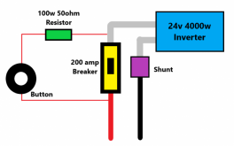
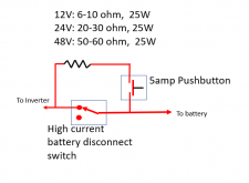
Up until Last week I had never heard of pre-charging a larger inverter before connecting the battery cables. I just lived with the spark. But I was watching a "Will" video about a DIY LFP build and saw that he used a resistor before connecting the Positive Terminal. This peaked my interest, and after poking around on the forum and asking a few questions, I decided it was time to put one on my system. I guess all manor of possible nasty things can happen and the little spark can be damaging to connections, DC breakers, and / or capacitors hidden deep within the inverter.
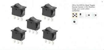
So I rounded up all the necessary parts and a few tools (like a cone shaped step drill bit) and it all arrived today. It was a fun project and works perfectly. The push button is very robust and about the size of a quarter. It is rated for 12v 60am or 24v 30amp according the seller on Amazon. I put in a Gold anodized aluminum 100w 50 OHM resistor and used 12awg stranded wire. Yeah most of that was overkill, but I wanted it to be robust. Very happy with the out come.
Please Let me know if I did anything wrong or what could have been done better. As always, its a work in progress.
Here is the Push Start Button and Resistor.
The squares on the mat are 1 inch.
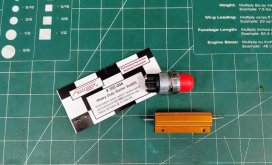
Here are the Links
Fastronix Heavy Duty Push Button Momentary Start Switch
LM YN 100 Watt 50 Ohm 5% Wirewound Resistor
Here is the Step Bit that makes the holes. I had never seen one of these before. I LOVE this tool
Titanium Step Drill Bit
Here is the Schneider Conext SW 4024 Before Install
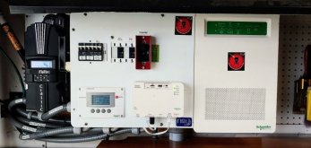
Here it is in its native habitat surrounded by the Midnite Soar E-Panel and the Classic 150 SCC
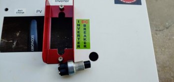
The Hole for the Push Button Came out Nice
Wiring it all up was pretty straight forward
I came off the back of the 250 amp breaker on the battery side
Thru the Push button and on to the resistor
Connected it at the main Positive (+) Inverter Input

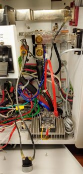
And here is how it all came Together.
I plan to place a label and instructions when I go to my office and get my label maker tomorrow.

Hope this helps anybody. Like I said, I had never heard of a Pre-Charger or Pre-Charging, but it sure makes sense, especially with hi-dollar gear. Thanks to this Forum and to all of you who answered my questions when I "hijacked" other threads.
MIke
So I rounded up all the necessary parts and a few tools (like a cone shaped step drill bit) and it all arrived today. It was a fun project and works perfectly. The push button is very robust and about the size of a quarter. It is rated for 12v 60am or 24v 30amp according the seller on Amazon. I put in a Gold anodized aluminum 100w 50 OHM resistor and used 12awg stranded wire. Yeah most of that was overkill, but I wanted it to be robust. Very happy with the out come.
Please Let me know if I did anything wrong or what could have been done better. As always, its a work in progress.
Here is the Push Start Button and Resistor.
The squares on the mat are 1 inch.

Here are the Links
Fastronix Heavy Duty Push Button Momentary Start Switch
LM YN 100 Watt 50 Ohm 5% Wirewound Resistor
Here is the Step Bit that makes the holes. I had never seen one of these before. I LOVE this tool
Titanium Step Drill Bit
Here is the Schneider Conext SW 4024 Before Install
Here it is in its native habitat surrounded by the Midnite Soar E-Panel and the Classic 150 SCC

The Hole for the Push Button Came out Nice

Wiring it all up was pretty straight forward
I came off the back of the 250 amp breaker on the battery side
Thru the Push button and on to the resistor
Connected it at the main Positive (+) Inverter Input


And here is how it all came Together.
I plan to place a label and instructions when I go to my office and get my label maker tomorrow.

Hope this helps anybody. Like I said, I had never heard of a Pre-Charger or Pre-Charging, but it sure makes sense, especially with hi-dollar gear. Thanks to this Forum and to all of you who answered my questions when I "hijacked" other threads.
MIke


