diy solar

diy solar

My Push Button Pre-Charger Install for the SW 4024 Inverter

Up until Last week I had never heard of pre-charging a larger inverter before connecting the battery cables. I just lived with the spark. But I was watching a "Will" video about a DIY LFP build and saw that he used a resistor before connecting the Positive Terminal. This peaked my interest, and after poking around on the forum and asking a few questions, I decided it was time to put one on my system. I guess all manor of possible nasty things can happen and the little spark can be damaging to connections, DC breakers, and / or capacitors hidden deep within the inverter.

So I rounded up all the necessary parts and a few tools (like a cone shaped step drill bit) and it all arrived today. It was a fun project and works perfectly. The push button is very robust and about the size of a quarter. It is rated for 12v 60am or 24v 30amp according the seller on Amazon. I put in a Gold anodized aluminum 100w 50 OHM resistor and used 12awg stranded wire. Yeah most of that was overkill, but I wanted it to be robust. Very happy with the out come.

Please Let me know if I did anything wrong or what could have been done better. As always, its a work in progress.

Here is the Push Start Button and Resistor.
The squares on the mat are 1 inch.

View attachment 42814

Here are the Links
Fastronix Heavy Duty Push Button Momentary Start Switch
LM YN 100 Watt 50 Ohm 5% Wirewound Resistor
Here is the Step Bit that makes the holes. I had never seen one of these before. I LOVE this tool
Titanium Step Drill Bit

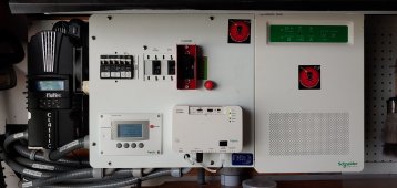
Here is the Schneider Conext SW 4024 Before Install
Here it is in its native habitat surrounded by the Midnite Soar E-Panel and the Classic 150 SCC

View attachment 42815


The Hole for the Push Button Came out Nice

View attachment 42816


Wiring it all up was pretty straight forward
I came off the back of the 250 amp breaker on the battery side
Thru the Push button and on to the resistor
Connected it at the main Positive (+) Inverter Input


View attachment 42817
View attachment 42819


And here is how it all came Together.
I plan to place a label and instructions when I go to my office and get my label maker tomorrow.

View attachment 42820

Hope this helps anybody. Like I said, I had never heard of a Pre-Charger or Pre-Charging, but it sure makes sense, especially with hi-dollar gear. Thanks to this Forum and to all of you who answered my questions when I "hijacked" other threads.

MIke

If I might make a suggestion.. When you activate it, monitor the temperature of your resistor.. its probably not an issue but those resistors are designed to be mounted to a heat sink with compound. I'm guessing the short duration pulse you're pushing through it won't have time to do anything but make it luke warm, but you should check it to be sure. You might have to attach a 1/4 thick aluminum plate under it as a heat sink.
I use a 10W power resistor in the same aluminum case and it heats up pretty quickly.
Thx. The resistor seems to have its own heat sink. So far I've notice very little heat
 
Well in testing a Conext SW inverter, it doesn't have an actual off switch (the big dc breaker is the off switch), one can only put the inverter in stand by. But the SW still has power going to the circuits.

When u turn off the breaker and then power it back up, the inverter is no longer in stand by, it is back on.

If I turn off the breaker and use the push button 50 ohm resistor, the SW seems to try to start powering on... But then starts clicking/blinking like it might be "oscillating" as @FilterGuy suggested earlier.

Assuming this is bad for the electronics, it might be That this whole resistor button idea is a bad idea for the Conext SW inverter series... Or I need either a higher than 50 ohm resistor to allow less current... Or a lower ohm resistor to perhaps have the SW power up but go into LV Disconnected?

I'm Kinda stumped. This project was supposed to be good for the inverter. I really don't want to be doing something that is not good at all.
I have the CSW4024, and I am pretty sure I see something different than you.

First off, I have not yet tried the resistor-based pre-charge on my unit. I've still got my lead acid AGM batteries.

If the inverter is in stand-by when I turn off the main breaker to disconnect everything from the battery, I'm pretty sure that when I turn it back on the inverter will power-up in stand-by. That is, there is a brief whirl of the fans in the inverter, but then it goes back to stand-by. My guess is that still will be too much for the pre-charge idea to work.

Second thing: The CSW does have a "DISABLED" state that I don't use, but I thought was kind of like an OFF state. If you hold down the ENABLE button on the inverter itself (not on the SCP) for some number of seconds, I think that makes it go into a DISABLED state. Since the CSW is supposed to return to it's previous state when the battery is reconnected, I think it should go back to DISABLED. I'm not sure, but that may take a few seconds. If it remains disabled, I would think the pre-charge should work.

Obviously I'm anxious to see how this works for you. If you are not able to get it to work, there is no point in my trying to buy the resistor and wire it in.
 
Well in testing a Conext SW inverter, it doesn't have an actual off switch (the big dc breaker is the off switch), one can only put the inverter in stand by. But the SW still has power going to the circuits.

When u turn off the breaker and then power it back up, the inverter is no longer in stand by, it is back on.

If I turn off the breaker and use the push button 50 ohm resistor, the SW seems to try to start powering on... But then starts clicking/blinking like it might be "oscillating" as @FilterGuy suggested earlier.

Assuming this is bad for the electronics, it might be That this whole resistor button idea is a bad idea for the Conext SW inverter series... Or I need either a higher than 50 ohm resistor to allow less current... Or a lower ohm resistor to perhaps have the SW power up but go into LV Disconnected?

I'm Kinda stumped. This project was supposed to be good for the inverter. I really don't want to be doing something that is not good at all.

I would worry about the same thing.
Does the SW inverter fully turn on when breaker is closed? Or does it wake up its controller, and hold off producing AC until given a command?
My SI 6048US displays a menu and "hold button to start." It should have a maximum power consumption of about 6W when not running.
What I might do (if using lithium rather than AGM) is connect a suitable resistance able to provide that power, and use a PTC fuse in series. That way, if I did start inverter with precharge resistor in the circuit, PTC fuse would open. (It resets automatically.)

6V/48V = 0.125A
If I want to deliver 99% of battery voltage, (0.01 x 48V)/0.125A = 12.5 ohms.
48V/12.5ohms = 4A peak surge current.
48V x 4A = 192W (unless a large resistor, won't last for long)

Using about 0.5A PTC fuse, if inverter starts to turn on it will trip the fuse. That will hold in the tripped position until load is removed and it is allowed to cool.

About 500' of 24 awg would be 12.5 ohms. That's 62' of 8 conductor LAN cable (shorter if finer gauge but I don't have the resistance table handy), wiring all the strands in series.

12.5A surge is plenty low limit for precharge surge. 125A or a bit more would be fine. But should be limited to peak current rating of PTC fuse.
The following for instance says 40A max, so want at least 1.2 ohms of wire. 6' x 8 strands of 24 awg would do that.

 
Well in testing a Conext SW inverter, it doesn't have an actual off switch (the big dc breaker is the off switch), one can only put the inverter in stand by. But the SW still has power going to the circuits.

When u turn off the breaker and then power it back up, the inverter is no longer in stand by, it is back on.

If I turn off the breaker and use the push button 50 ohm resistor, the SW seems to try to start powering on... But then starts clicking/blinking like it might be "oscillating" as @FilterGuy suggested earlier.

Assuming this is bad for the electronics, it might be That this whole resistor button idea is a bad idea for the Conext SW inverter series... Or I need either a higher than 50 ohm resistor to allow less current... Or a lower ohm resistor to perhaps have the SW power up but go into LV Disconnected?

I'm Kinda stumped. This project was supposed to be good for the inverter. I really don't want to be doing something that is not good at all.

I see where you're at!
The Precharge Resistor isn't needed if all you're doing is turning the inverter's internal breaker on and off. The precharger is used if you isolate the battery bank from the inverter (via main battery breaker), then reconnect the power.

You're thinking that breaker on the inverter is an isolation device like a circuit breaker should be, but it is probably not.

Same thing with my Sunny Islands by the way.

The precharge resistor is used for a few seconds before you allow a direct connection between the battery and the inverter. In my system, a BMS (Battery Management System), has control over a 400 amp contactor between the battery and the inverter. Before activating that contactor, we bleed power through the precharge resistor for 5 seconds.. then the contactor closes, then we flip the inverter's internal breaker on.
 
One more thing you can test.

Turn off the inverter's breaker and isolate the battery from the inverter via breaker or pulling the negative terminals away.

Now measure the voltage at the inverter's battery terminals.. I bet you find battery voltage slowly falling over several hours.
 
I see where you're at!
The Precharge Resistor isn't needed if all you're doing is turning the inverter's internal breaker on and off. The precharger is used if you isolate the battery bank from the inverter (via main battery breaker), then reconnect the power.

You're thinking that breaker on the inverter is an isolation device like a circuit breaker should be, but it is probably not.

Same thing with my Sunny Islands by the way.

The precharge resistor is used for a few seconds before you allow a direct connection between the battery and the inverter. In my system, a BMS (Battery Management System), has control over a 400 amp contactor between the battery and the inverter. Before activating that contactor, we bleed power through the precharge resistor for 5 seconds.. then the contactor closes, then we flip the inverter's internal breaker on.

I find that breaker in Sunny Island isolates its capacitors from the battery. So I think a precharge resistor is desired when charging those caps.
Unless you muck around inside you can't put a precharge resistor around its breaker.
If you have an external switch with precharge resistor, you can open that switch, close SI breaker, apply precharge circuit, close switch.
 
The breaker for my Schneider Conext SW is a separate 200 amp DC breaker. When the DC breaker and the AC input breaker are both off, there is no power going to the SW at all. The inverter itself has no breaker or on/off switch. The SCP (system control panel) which is sold separately has a dedicated button to disable the inverter portion of the SW but it does not power the unit down. It only shuts off the inverter side of the inverter / charger.

If the inverter is in stand-by when I turn off the main breaker to disconnect everything from the battery, I'm pretty sure that when I turn it back on the inverter will power-up in stand-by. That is, there is a brief whirl of the fans in the inverter, but then it goes back to stand-by. My guess is that still will be too much for the pre-charge idea to work.
@Horsefly you are correct. If I power off in "Inverter Disabled" mode. It does indeed power back on via the main 200amp DC breaker in "Inverter Disabled"

Second thing: The CSW does have a "DISABLED" state that I don't use, but I thought was kind of like an OFF state. If you hold down the ENABLE button on the inverter itself (not on the SCP) for some number of seconds, I think that makes it go into a DISABLED state. Since the CSW is supposed to return to it's previous state when the battery is reconnected, I think it should go back to DISABLED. I'm not sure, but that may take a few seconds. If it remains disabled, I would think the pre-charge should work.
I tried pressing and holding the external button on the SW. Nothing happened even after some seconds. Maybe I did not hold it long enough. I tried it with the inverter Disabled and AC support mode off. Still nothing.

So I power down with the main breaker, and If I use the precharge 50 ohm resistor, the unit blinks/clicks rhythmically and looks as if it is trying to turn on but never fully powers up until I engage the main breaker. Also, the Combox (the external network communication box for the SW) also blinks in that same rhythm with the SW Inverter/Charger as it "tries" to start under the limited current of the resistor.

Attached is a link to a video (waiti for it ... its still processing) of what is happening. I do not think you can hear the clicking, but you can see the blinking.

 
I just I just realized in that video, the s w does not seem to even turn the power to the inverter on even after the breaker is engaged, until the unit qualifies the incoming power. So maybe the s w inverter does not need a pre charger
 
The breaker for my Schneider Conext SW is a separate 200 amp DC breaker. When the DC breaker and the AC input breaker are both off, there is no power going to the SW at all. The inverter itself has no breaker or on/off switch. The SCP (system control panel) which is sold separately has a dedicated button to disable the inverter portion of the SW but it does not power the unit down. It only shuts off the inverter side of the inverter / charger.


@Horsefly you are correct. If I power off in "Inverter Disabled" mode. It does indeed power back on via the main 200amp DC breaker in "Inverter Disabled"


I tried pressing and holding the external button on the SW. Nothing happened even after some seconds. Maybe I did not hold it long enough. I tried it with the inverter Disabled and AC support mode off. Still nothing.

So I power down with the main breaker, and If I use the precharge 50 ohm resistor, the unit blinks/clicks rhythmically and looks as if it is trying to turn on but never fully powers up until I engage the main breaker. Also, the Combox (the external network communication box for the SW) also blinks in that same rhythm with the SW Inverter/Charger as it "tries" to start under the limited current of the resistor.

Attached is a link to a video (waiti for it ... its still processing) of what is happening. I do not think you can hear the clicking, but you can see the blinking.

Hmmm. I'm out of my depth and only guessing at this point, but I would think that the precharge is still helping to reduce the huge inrush. I think connecting the battery while you are still holding down the button is probably significantly reducing the inrush. However, I don't know if it is doing any harm to the CSW (or SCP, or Combox) of having it be in that flashing, not quite on, not quite off state for a few seconds. I'd have to think it is not causing any harm.

By the way, you and I have a pretty similar set up. I've got the CSW4024, SCP, and the Schneider MPPT60-150. Of note, you and I are both using the Midnite E-Panel. I really like it. Attached is a pic of my gear. SAM_3014.jpg
 
I see where you're at!
The Precharge Resistor isn't needed if all you're doing is turning the inverter's internal breaker on and off. The precharger is used if you isolate the battery bank from the inverter (via main battery breaker), then reconnect the power.
I'm disconnecting the main breaker isolating the inverter from the battery
 
I just I just realized in that video, the s w does not seem to even turn the power to the inverter on even after the breaker is engaged, until the unit qualifies the incoming power. So maybe the s w inverter does not need a pre charger
I don't think I would come to that conclusion. The large capacitors on the front-end are meant to smooth out the DC power coming in. I would imagine they would have to be in the circuit as the CSW is qualifying the DC power. The problem is, you are probably not going to prevent at least some arcing when you throw the switch, but it should be small enough to not be a bother.
 
By the way, you and I have a pretty similar set up. I've got the CSW4024, SCP, and the Schneider MPPT60-150. Of note, you and I are both using the Midnite E-Panel. I really like it. Attached is a pic of my gear. View attachment 50888
Yours is clearly much cleaner. LOL
 

Attachments

  • 0529211337.jpg
    0529211337.jpg
    1.2 MB · Views: 16
I might tinker with a smaller then a larger cap for fun. truth is when everything is humming along I hardly ever turn off the inverter anyway
 
Back
Top