Hedges
I See Electromagnetic Fields!
- Joined
- Mar 28, 2020
- Messages
- 20,508
Wait - Is that mine our yours?! How did you take a picture inside my e-Panel?! ?
Remotely enabling the camera in your smartphone. We're listening to you talk to yourself, too.


Wait - Is that mine our yours?! How did you take a picture inside my e-Panel?! ?
I find that breaker in Sunny Island isolates its capacitors from the battery. So I think a precharge resistor is desired when charging those caps.
Unless you muck around inside you can't put a precharge resistor around its breaker.
If you have an external switch with precharge resistor, you can open that switch, close SI breaker, apply precharge circuit, close switch.
I'm a bit confused. First, I don't think I've ever heard anyone claim that a pre-charge is needed on a SCC. Second, do you have two separate feeds from your battery, one to the Inverter and one to the charge controller? I'm making an assumption that you are doing a DIY battery and have a BMS. Is it that you have a separate port BMS (instead of common port BMS)?I will be wiring a resistor pre-charge circuit to both my Victron Multiplus II and my 2 epever MPPT Solar Charge Controller Tracer4215BN,
I have noticed small sparks when hooking up an SCC, but I have never felt they were large enough to worry about.First, I don't think I've ever heard anyone claim that a pre-charge is needed on a SCC.
Correct....You don't have something like that on a solar charge controller, at least not nearly at the same magnitude.
Agreed. Regardless, my precharge circuit precharges the positive bus bar. As long as the scc breaker is on, its capacitors will fill. My battery monitor also lights up during precharge (as I would expect with any low power consumer).I have noticed small sparks when hooking up an SCC, but I have never felt they were large enough to worry about.
The plan is the batteries connected to a shunt on the negative side then to the negative bus bar, the positive lead to a 250 amp fuse on each battery then to the positive busbar. Switches to control 12 volt connection to the Multiplus and a resistor pre charge circuit. I want breakers in the SCC wiring also with a precharge circuit. I believe I have seen Will precharge both his inverters and his SCCs when he hooks them up. Resistors and 12 guage wire are pretty cheap so even if overkill it will not break the bank. The bms is common portegnI'm a bit confused. First, I don't think I've ever heard anyone claim that a pre-charge is needed on a SCC. Second, do you have two separate feeds from your battery, one to the Inverter and one to the charge controller? I'm making an assumption that you are doing a DIY battery and have a BMS. Is it that you have a separate port BMS (instead of common port BMS)?
Anyway, others can chime in here but a separate pre-charge for the SCC does not seem needed. The purpose of the pre-charge is to charge up the large capacitors on the front-end of an inverter, which can look like a short circuit to the batteries for a small fraction of a second. Doing the pre-charge allows the capacitors to charge up gently before you connect the battery. SCC's don't have that large capacitor on the battery side.
The test would only be viable for the specific SCC that you tested, right? The spark that i experienced when I first connected and tested my panels/mppt months ago wasn't too extreme. I installed through breakers for the installation in the RV.Just hopping in to say I think its pretty cool and thoughtful to precharge the SCC Capacitance in addition to Inverter Capacitance
I’m trying to build a system that lasts a long time, and personally think managing inrush currents responsibly is a good way to ensure long operation.
Look what you all have done to me, now I’m feeling curious to set up a hall effect current sensor on a wire and log the data while connecting it from battery to victron bluesolar SCC (that’s the type i have available on hand)! ???
In order to say that it’s unnecessary or overly cautious I need the data log from the above paragraph experiment. Haven’t done that yet..
Totally agree. Have not encountered an SCC that made a big enough spark to concern me. Inverters, yes.So I don't think precharge matters for MPPT, just for inverter. Besides, you probably connect MPPT once and leave it connected, but you might disconnect inverter more often to turn it off.
Yes absolutely.The test would only be viable for the specific SCC that you tested, right?
But I do think it would be cool if the precharge circuit could be more intelligent, maybe even logging inrush current on each use and intelligently indicating whether to continue with system boot up.
Samlex evo inverters have this integration. samlex has taken some effort to facilitate and incorporate the use of lifepo4 with the evos (not the precharge part, though).Simple enough to do, if the FET or relay disconnect has communication with the load.
Inrush limiter IC with "power good" output signal is common in electronics design.
But I've seen problems with it, when the loads downstream weren't wired to that "power good" signal, instead watched supply voltage to make their own decision. Lots of FETs in the inrush circuit got burned up.
Future inverters designed for lithium batteries ought to integrate the disconnect function (service to BMS) and inrush limiting. Or, BMS should do inrush limiting and provide signal for inverter. They ought to be on speaking terms anyway, to best manage the battery.


 www.adafruit.com

 www.pololu.com

Cool idea.ADS1115 16-Bit ADC
View attachment 5932715 usdADS1115 16-Bit ADC - 4 Channel with Programmable Gain Amplifier
For microcontrollers without an analog-to-digital converter or when you want a higher-precision ADC, the ADS1115 provides 16-bit precision at 860 samples/second over I2C. The chip can be ...
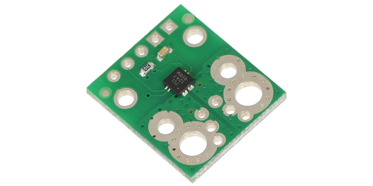
ACS711EX Current Sensor Carrier -31A to +31A
View attachment 59328
4 usdPololu - ACS711EX Current Sensor Carrier -31A to +31A
This board is a simple carrier of Allegro’s ±31 A ACS711 Hall effect-based linear current sensor with overcurrent fault output, which offers a low-resistance (~0.6 mΩ) current path and electrical isolation up to 100 V. This version accepts a bidirectional current input with a magnitude up to 31...
and a generic wire wound resistor that looks like this: (be sure to select resistor ohm value carefully based on system voltage of course)
View attachment 59330
these are the components i’m using to experiment with current monitoring precharge circuit. samd21 microcontroller. ina219 to monitor bus voltage for situations with VBUS<26V

That kind of inrush might not harm the inverter, but it might blow fuses. class-t fuses @ $40 a piece make a $20 precharge circuit worth it.Cool idea.
I'm not sure the little ADC board is needed if you can round up an ESP8266 or ESP32 board, both of which already have an ADC. The current sensor is another animal. If you want current sensing, that looks like a good solution.
Personally, I think we (on this board) have kind of over-played the whole "pre-charge" thing. I certainly don't know the whole population of inverters, but I think many - maybe most - inverters would be pretty hard to harm with the inrush to their front-end capacitors. I am very convinced that SCC's don't need to mess with this.
Having said that, I put a pre-charge circuit into my new LFP box, just because I could. Rube Goldberg was a genius!
I agree....That kind of inrush might not harm the inverter, but it might blow fuses. class-t fuses @ $40 a piece make a $20 precharge circuit worth it.