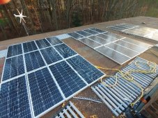
It started with a four-day outage one July two years ago. Being on a well, no electricity = no water. No water = no flushing. No flushing = I won’t go there. I wanted a backup generator but was outvoted: the family insisted on something independent and renewable. What better than the sun?
Beginning with a pair of HQST 100-Watt 12 Volt Polycrystalline Solar Panels and a 500-Watt Kyng Power Solar Generator Portable Power Station UPS Battery, I started my adventure. In no time at all, I graduated to four Richsolar 100-Watt 12 Volt Monocrystalline Solar Panels, a Renogy Rover 20-Amp 12V/24V MPPT Solar Charge Controller with a BT-1 Bluetooth Module, and a BLUETTI EB150 1500Wh Emergency Battery Backup Unit.
Then things got a little crazy. I built a pergola the summer before and before you know it, there were twelve HQST 100-Watt 12 Volt Polycrystalline Solar Panels sitting on top of it.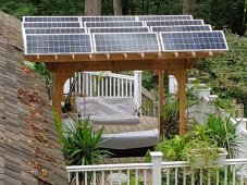 Well, all that electricity had to go somewhere, so I passed it through an
 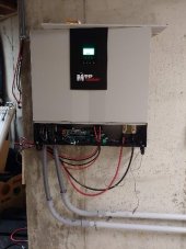 MPP SOLAR 5000w Split Phase Solar Inverter and into four 12-Volt 200-AmpHour Lead-Acid batteries
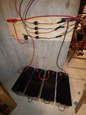 wired in a series. (I know, but they were cheap)
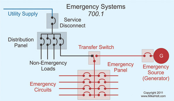
All of this stuff would get wired into the house somehow by a licensed electrician who would take care of permits and inspections. I sent a diagram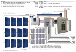 of how the overall configuration was supposed to turn out. In retrospect, it may have been a little intimidating. After the two I called said they were too busy, I got a little impatient and things may have gotten out of hand.
The house is large with 200-Amp service. I knew I could never get to a backup system that large. Instead, I installed a secondary breaker box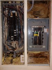 to split out all the must-have circuits. The original box was completely full anyway.
To make things even more interesting, MPP insists their controllers be installed on a block or concrete wall for safety. Luckily, I had one only a finished ceiling and finished load bearing wall away. Two eighteen-foot runs of one-inch conduit encasing three eight-gauge conductors (plus ground) later, I had contact. One came out of the main breaker box with a dedicated breaker and into the MPP. The second came out of the MPP and into the auxiliary breaker box to pass through a pair of interlocked cutover breakers. The MPP will switch between solar and utility automatically, but I can also manually override. Things like the water pump, furnaces, central air, water heater, refrigerators, garage and garage door openers, and all network and WiFi-supporting circuits got switched over to the battery backup system..
Before you know it, our four little batteries became eight.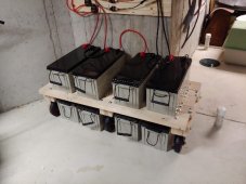 Summer arrived. As the trees and flowers grew, so did the system. A/C plus water-pump taxed things a bit too much. Did I mention the main furnace, A/C, and water pump are all 2-phase, 240-Volts? That’s what led to choosing that model of MPP in the first place.
Enter a second MPP,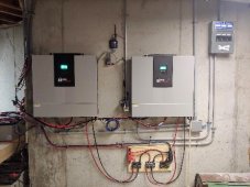 for a combined 10kW of output, and over time, eight more batteries
 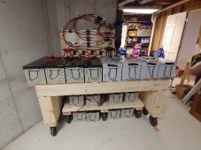 for 38.4 thousand Watt-hours of storage, and thirty-six more solar panels
 bringing us to a theoretical 4,800 Watts of solar input. I say theoretical because this is, after all, Michigan. In winter, bright, cloudless sunlight is measured in hours. I am set up so I can install a third MPP should climate change work out in my favor.
Anyway, I am hedging my bets. I installed a horizontal wind turbine and a vertical wind turbine and passed them through a Renogy Rover 60 Amp 12V/24V/36V/48V DC Input MPPT Solar Charge Controller. Luckily, I managed to find the most wind-free spots on the property. Together, they generate more frustration than energy, which is OK. I haven’t figured out how to fix the “Charge not ready” message the Rover keeps displaying anyway.
My last act of uncivil disobedience was to install an Emporia Smart Home Energy Monitor with 16 50A Circuit Level Sensors.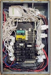 It gives me valuable and detailed information on consumption so I can more accurately assess how many days the battery backup will last. Needless to say, the Battery Backup Breaker Box is now filled to the gills. I have room for a couple more circuits at best. Decisions, decisions.
And please, not a word of this to the Township Department of Buildings and Inspection.
Beginning with a pair of HQST 100-Watt 12 Volt Polycrystalline Solar Panels and a 500-Watt Kyng Power Solar Generator Portable Power Station UPS Battery, I started my adventure. In no time at all, I graduated to four Richsolar 100-Watt 12 Volt Monocrystalline Solar Panels, a Renogy Rover 20-Amp 12V/24V MPPT Solar Charge Controller with a BT-1 Bluetooth Module, and a BLUETTI EB150 1500Wh Emergency Battery Backup Unit.
Then things got a little crazy. I built a pergola the summer before and before you know it, there were twelve HQST 100-Watt 12 Volt Polycrystalline Solar Panels sitting on top of it.
 Well, all that electricity had to go somewhere, so I passed it through an
  MPP SOLAR 5000w Split Phase Solar Inverter and into four 12-Volt 200-AmpHour Lead-Acid batteries
 wired in a series. (I know, but they were cheap)
All of this stuff would get wired into the house somehow by a licensed electrician who would take care of permits and inspections. I sent a diagram
 of how the overall configuration was supposed to turn out. In retrospect, it may have been a little intimidating. After the two I called said they were too busy, I got a little impatient and things may have gotten out of hand.
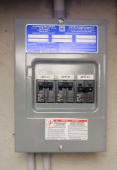
The house is large with 200-Amp service. I knew I could never get to a backup system that large. Instead, I installed a secondary breaker box
 to split out all the must-have circuits. The original box was completely full anyway.
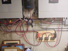
To make things even more interesting, MPP insists their controllers be installed on a block or concrete wall for safety. Luckily, I had one only a finished ceiling and finished load bearing wall away. Two eighteen-foot runs of one-inch conduit encasing three eight-gauge conductors (plus ground) later, I had contact. One came out of the main breaker box with a dedicated breaker and into the MPP. The second came out of the MPP and into the auxiliary breaker box to pass through a pair of interlocked cutover breakers. The MPP will switch between solar and utility automatically, but I can also manually override. Things like the water pump, furnaces, central air, water heater, refrigerators, garage and garage door openers, and all network and WiFi-supporting circuits got switched over to the battery backup system..
Before you know it, our four little batteries became eight.
 Summer arrived. As the trees and flowers grew, so did the system. A/C plus water-pump taxed things a bit too much. Did I mention the main furnace, A/C, and water pump are all 2-phase, 240-Volts? That’s what led to choosing that model of MPP in the first place.
Enter a second MPP,
 for a combined 10kW of output, and over time, eight more batteries
  for 38.4 thousand Watt-hours of storage, and thirty-six more solar panels
 bringing us to a theoretical 4,800 Watts of solar input. I say theoretical because this is, after all, Michigan. In winter, bright, cloudless sunlight is measured in hours. I am set up so I can install a third MPP should climate change work out in my favor.
Anyway, I am hedging my bets. I installed a horizontal wind turbine and a vertical wind turbine and passed them through a Renogy Rover 60 Amp 12V/24V/36V/48V DC Input MPPT Solar Charge Controller. Luckily, I managed to find the most wind-free spots on the property. Together, they generate more frustration than energy, which is OK. I haven’t figured out how to fix the “Charge not ready” message the Rover keeps displaying anyway.
My last act of uncivil disobedience was to install an Emporia Smart Home Energy Monitor with 16 50A Circuit Level Sensors.
 It gives me valuable and detailed information on consumption so I can more accurately assess how many days the battery backup will last. Needless to say, the Battery Backup Breaker Box is now filled to the gills. I have room for a couple more circuits at best. Decisions, decisions.
And please, not a word of this to the Township Department of Buildings and Inspection.


