diy solar

diy solar

My Tesla batteries are dying...Saved them!

heresay from claims about other devices it is integrated into at an OEM level, not DIY jobs.
<snip>
TL;DR military and medical are unqualified subjective terms that anyone may use when they feel like it. no claims of specific standard compliance should be inferred from this claim.

JBD 120A 12V model meets my personal definition of what it means to functionally be military and medical grade.
I'm glad I asked.
 
i’ve said my bit, time to move on.

the disregard for safety of life in this thread and misfocused effort could be improved upon.

safety disconnects are called for with Lithium Chemistries

understanding real specifications is better than semantic duels ✌️
 
As for a BMS, probably not. Again they just don't see enough cycling to go out of balance. Cells 3-6 were all within .003v (4.017-4.020) after 15 months of use! That makes me continue to believe a BMS is unnecessary for my situation.

Even with BMS it is a very explosive battery. Use it and do not misuse it.


You don't "year ya'll." You don't care what we're saying
Ding ding ding, you win a prize. Yet you still typed and typed, thinking what...if you berate me enough I'll see it your way? You trying to save everyone on the internet?

Curiouscarbon at least tried to say the same without being a d**ick.
 
Ding ding ding, you win a prize. Yet you still typed and typed, thinking what...if you berate me enough I'll see it your way? You trying to save everyone on the internet?

Curiouscarbon at least tried to say the same without being a d**ick.
Arrogant and cavalier.
 
@sed6: What is the maximum balancing current that you used? 5A? Also, what wire gauge are your Tesla module balance leads?
 
Last edited:
@sed6: What is the maximum balancing current that you used? 5A? Also, what wire gauge are your Tesla module balance leads?
5a is correct. I just bought and tried the HTRC C150 balance charger. It worked well. Dunno on the wire gauge, used the same size wire as Tesla runs throughout the battery and back to the stock charging board.
 
I hear ya'll but what happens when the BMS fails? What happens if the fire department doesn't show up? Life is full of risk. Show me an example of someone burning down their house with a Tesla battery and I'll show you someone who still doesn't care. Just because Will is afraid of LiPo's doesn't mean we all have to be.
Thanks for the info and your DIY powerwall posts.
I won’t get into the weeds on Tesla battery fires, but I show the princess fire often to my clients.
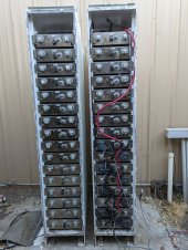
I ended up with 32 Tesla “model S” type batteries in steel cases put together by Princeton Battery (GTIB30’s). They had set at 2.2V for a couple of years and I brought them back slowly and carefully over a 60 day period with a combination of a small variable voltage and current battery charger and (10 amps max mostly around 4 amps) and then SHORT high current charges from a Victron Blue Smart 24/12 (I could dial the voltage down). I also carefully noted the temps and voltages but did it without a BMS.

NOTE: I WOULD NOT DO IT AGAIN WITHOUT A BMS

I got 8 of them working reasonably well and then put together a SIMP BMS configuration and started experimenting and monitoring.
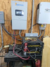
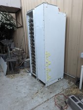
My old SMA 8KW from 2008 died so installed a DEYE (Sol-Ark 12K) and a Discover 42-48-6650, it worked well and tested both the SOK and the EG4 48V batteries for TOU arbitrage.

Put 8 of the Tesla’s in a steel case outside my home metal shop and hand-built the molex connectors and the wiring harness for the SIMP BMS to interface with the existing Tesla balancing boards. (this was the hardest part for I am not young, and my vision is not what it used to be.)

The Simp BMS is not plug and play, not intuitive, and not for anyone who gets frustrated at failure. It a pain and requires networking understanding, RS485 knowledge, firmware upgrade and serial interface experience. It works one way on Termite for configuration and needs something like Secure CRT for monitoring and logging. I have not figured out how to use Secure CRT on it for configuration purposes, and I have 30 yrs of experience in serial interface programs.

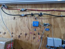
I did install a current CT and a CONTACTOR failsafe (requires power to charge or discharge the battery) The contactor works perfectly and is easily configurable for fail-safe, and the CT is unreliable in my opinion, but I have other ways to monitor the current.

I experimented with charge and discharge voltages, it worked well for a few weeks and then I put in another 8 batteries and implemented TOU arbitrage and moved on to other projects.

A few months went by and I checked it a few times a week and noticed Module 09 cell 52 was creeping close to 4.12v and we had a 200mv delta in the 96 cells (0-95)
It disconnected at 4.12 and I played around with voltages (dropping the charging voltage) but it still disconnected. I had to go in and modify the balancing voltage down to a point we could get active balancing enough hours a day to drop the delta down below 160mv.
I have a bad cell and will pull it out of the pack before the summer when the charge and discharge accelerates the delta and my self-imposed pack disconnect. I suspect there will more bad ones show up as I add the 2nd 16 batteries.
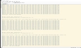
Module #8 23.58V Cell42: 3.93V Cell43: 3.93V Cell44: 3.93V Cell45: 3.93V Cell46: 3.93V Cell47: 3.93V Neg Term Temp: 15.86C Pos Term Temp: 15.10C
Module #9 23.72V Cell48: 3.98V Cell49: 3.89V Cell50: 3.97V Cell51: 3.89V Cell52: 4.11V Cell53: 3.89V Neg Term Temp: 15.95C Pos Term Temp: 15.16C
Module #10 23.40V Cell54: 3.91V Cell55: 3.90V Cell56: 3.90V Cell57: 3.90V Cell58: 3.90V Cell59: 3.90V Neg Term Temp: 15.67C Pos Term Temp: 14.82C

Modules: 16 Cells: 96 Strings: 8 Voltage: 47.122V Avg Cell Voltage: 3.927V Low Cell Voltage: 3.886V High Cell Voltage: 4.111V Delta Voltage: 225mV Avg Temp: 15.792C

The bottom line is the fail-safe contactor is REALLY important and a cell can go bad in the middle of the pack. Probably why the units failed.
This was all done in 2021 and 2022, and sorry I did not have the time to document it, but life gets busy (GRIN) that is a good thing.

Currently, my Sol-Ark charge voltages are 46V and battery empty is 41V
 

Attachments

  • IMG_20220801_200255.jpg
    IMG_20220801_200255.jpg
    181.5 KB · Views: 25
  • PXL_20220531_025741817.jpg
    PXL_20220531_025741817.jpg
    207.7 KB · Views: 25
  • PXL_20220531_031727016.jpg
    PXL_20220531_031727016.jpg
    172.8 KB · Views: 26
  • PXL_20230329_201159255.jpg
    PXL_20230329_201159255.jpg
    300.4 KB · Views: 21
  • Screenshot 2023-03-29 144854.jpg
    Screenshot 2023-03-29 144854.jpg
    423.5 KB · Views: 22
BTW. I may not have been clear on how the SIMP BMS is being used for safety. I have it set so if any one cell reaches 4.12v, the energizing circuit is disabled and no charging can happen. It can also be set for temperature trip and probably a few other variables, but with a pack this large and using for ESS rather than running a vehicle, the charge and discharge currents are low.
It works flawlessly in my experience. I of course tested the cutoff and was grateful when it shut down.
Yes I know I can go to a higher voltage but safety was my motivator rather than efficiency.
text from Tesla blog:

Avoiding very high and very low states of charge. Voltages over 4.15V/cell (about 95 percent state of charge [SOC]) and voltages below 3.00V/cell (about 2 percent SOC) cause more stress on the insides of the cell (both physical and electrical).

The SIMP BMS can monitor I think 64 batteries and using the Tesla cards that are already in the batteries, appears to auto populate in the order of cabling. There is an in and out wiring scheme off each Tesla balancing board.

The below setting are just experimenting and little real scientific research. I just needed it to work and shut off when voltages got too high.


1 - Cell Over Voltage Setpoint: 4150mV
2 - Cell Under Voltage Setpoint: 3000mV
3 - Over Temperature Setpoint: 200.00C
4 - Under Temperature Setpoint: 2.00C
5 - Cell Balance Voltage Setpoint: 3100mV
6 - Balance Voltage Hystersis: 40mV
7 - Ah Battery Capacity: 100Ah
8 - Pack Max Discharge: 30.00A
9 - Cell Discharge Voltage Limit Setpoint: 3200mV
0 - Slave strings in parallel: 8
a - Cells in Series per String: 12
b - setpoint 1: 3100mV
c - SOC setpoint 1:10%
d - setpoint 2: 4100mV
e - SOC setpoint 2: 90%
g - Storage Setpoint: 3800mV
h - Discharge Current Taper Offset: 300mV
j - Discharge Current Temperature Derate : 40.00C
k - Cell Discharge Voltage Hysteresis: 200mV


MENU
Debugging Paused
Firmware Version : 220505
b - Battery Settings
a - Alarm and Warning Settings
e - Charging Settings
c - Current Sensor Calibration
k - Contactor and Gauge Settings
i - Ignore Value Settings
d - Debug Settings
x - Experimental Settings
R - Restart BMS
q - exit menu
 

Attachments

  • Simp BMS Setup Manual V0.29.pdf
    1.5 MB · Views: 2
Back
Top