diy solar

diy solar

Name your price for drawing up a simple diagram. I will pay it!!! Please! Desperate.

No.
Actually I'm only guessing.
I may or may not have watched his video.

There are 3 parts to the integration.
1. signalling with there communication wire.
2. configuration to make one unit the master and the other the slave.
3. AC wiring to be done by and electrician.
there's a video link in my post that shows Will hooking up two inverters to a panel in parallel split phase. I thought that was what I needed. I wish my diagram was able to be seen. No offense. I really appreciate your trying to help.
 
Ok, so back to hiring an electrician. So I may as well have the local guy come do this for 250$ an hour. This is what I was hoping to avoid. Maybe I'll just wire them the way Will has them and not bother connecting them. forget about 240. Seems to be outside of the DIY element once I try to use them as the growatt manual suggest. parallel split phase.
Good luck finding an electrician to do steps 1 and 2.
 
exactly. Round and round I go. I feel like I'm never going to get this.
I updated my drawing.
I'm sure others can see your drawing just not me.
The Growatt manual covers the integration and it looks pretty simple.
 
This link will get you to the manual
Parallel Installation Guide round about page 27

I couldn't make it any simpler than they already have.
 
This link will get you to the manual
Parallel Installation Guide round about page 27

I couldn't make it any simpler than they already have.
it says that all inverters are connected to the same batteries and the diagram shows the wires summed from both inverters. Not two distinct systems.
 
starting on page 25
You want "Parallel Operation in Split Phase'

Suit yourself.
on the online manual that is on page 34. The original method you were describing in your diagram. That is parallel operation in split phase? I guess I thought based on their picture that the batteries needed to be summed. Not so?
 
on the online manual that is on page 34. The original method you were describing in your diagram. That is parallel operation in split phase? I guess I thought based on their picture that the batteries needed to be summed. Not so?
I can't see the picture but no the batteries do not need to be summed.
 
I can't see the picture but no the batteries do not need to be summed.
So if I did want to do it as they suggest, and based on your earlier calculations, the fault amps were 91.91 each. Does that mean I buy two 100amp busbars one for each?
 
Man the Plea sounds really desperate.
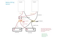
I drew up the battery hook up side with MS paint just now. yeah it looks like fourth grade work but at least it can get the Inverters up and running.
I will try to find some time if no one else volunteers to do the AC side. I assume the PV is not an issue.
I would use 150A Class T Fuses and make sure wires are crimped properly.


MyGrowatt_BatWiring.jpg
 
Man the Plea sounds really desperate.
I drew up the battery hook up side with MS paint just now. yeah it looks like fourth grade work but at least it can get the Inverters up and running.
I will try to find some time if no one else volunteers to do the AC side. I assume the PV is not an issue.
I would use 150A Class T Fuses and make sure wires are crimped properly.


View attachment 80711
OH MY GOD!! Thank you sooooooo much. It's beautiful and yes, I am desparate. lol,. Yes, this is exactly what I needed. So, the busbars need to be able to handle how many amps? Also, would 4 AWG work or no. Not going far, less than two feet. I only ask because I do have those wires for the batteries but I can totally return them no problem if 2 is better. I can't tell you how much I appreciate this. Yes, pv is not an issue. I can figure that part out but the AC side would be a massive help. Please let me know how I can pay you for your time. This is exactly what I was trying to get.
 
OH MY GOD!! Thank you sooooooo much. It's beautiful and yes, I am desparate. lol,. Yes, this is exactly what I needed. So, the busbars need to be able to handle how many amps? Also, would 4 AWG work or no. Not going far, less than two feet. I only ask because I do have those wires for the batteries but I can totally return them no problem if 2 is better. I can't tell you how much I appreciate this. Yes, pv is not an issue. I can figure that part out but the AC side would be a massive help. Please let me know how I can pay you for your time. This is exactly what I was trying to get.
Your welcome and of course in the spirit of DIY there is no charge.
Yes 4 AWG would work given that each Growatt can only draw about 70A but I would feel better with some extra margin but if you have the cable on hand wire it up and at least get a feel for what your doing and then you can swap the cable out at a later date.

300 Amp Busbar is more than enough.
I just did a quick search and saw this one, but please look at the reviews and see what is the best quality you want to buy.
Amazon Busbar

Edit:
Just noticed I did not label the two negative wires that go up to the Inverter. Those must be the same length as E&F / G&H. So if E&F add up to 7ft then G&H must be 7ft and the two negatives must be 7ft. Always look at what is going to be the longest wire and make that first then make the copies to match the length.

I am loging out now for several hours so good luck.
 
Last edited:
Your welcome and of course in the spirit of DIY there is no charge.
Yes 4 AWG would work given that each Growatt can only draw about 60A but I would feel better with some extra margin but if you have the cable on hand wire it up and at least get a feel for what your doing and then you can swap the cable out at a later date.

300 Amp Busbar is more than enough.
I just did a quick search and saw this one, but please look at the reviews and see what is the best quality you want to buy.
Amazon Busbar

Edit:
Just noticed I did not label the two negative wires that go up to the Inverter. Those must be the same length as E&F / G&H. So if E&F add up to 7ft then G&H must be 7ft and the two negatives must be 7ft. Always look at what is going to be the longest wire and make that first then make the copies to match the length.

I am going logging out now for several hours so good luck.
Thank you from the bottom of my heart. This has been such a journey. You have been so helpful. Thank you thank you thank you.
 
I am going to try and keep it light on the Tech Jargon because I know you have been bombarded by it.

I am home now and just wanted to look at a few things again and something kind of stuck out at me.
You have 16 panels and I assume you were thinking of running a four in series and then parallel them with another 4 in series (4S2p) type configuration. The Unconnected/Open Circuit voltage (Voc) . from those panels is
The one thing I do not like and your just going to have to test and find out is if that 4S2P is going to be enough for that Inverter. According to the Manual the startup voltage from the panels needs to at least 150Vdc. Your panels are going to produce 41.49Vdc each x 4 panels is 165Vdc and a working voltage of 133V The manual says +/-10Vdc so it could be 160Vdc to activate the Inverter and a minimum working voltage of 120Vdc. That 5-15Vdc wiggle room is a little close for my comfort and I somehow think Will needed 130 working volts to get his running. Maybe someone with the same model inverter can chime in.

I would have felt more comfortable with a 5S2P which would be 207Vdc and working Voltage of 166V with Aprox 19 Amp. That is nicely inspec with this Inverter 250V and 22Amp max capabilities.

The 4S2P setup is nothing to worry about, but just make sure you have room to mount another panel in each series string if the Inverter will not start charging the batteries. The down side if that happens is that you would need four more panels. I think you might be okay but I just wanted you to be aware that if nothing is happening then this could be the reason. Also the MPPT tends to track better when they have more range to play with.
 
Last edited:
Back
Top