diy solar

diy solar

Need advice for a BMS for use with a large BMW battery pack.

Dacflyer

New Member
Joined
Jun 5, 2020
Messages
349
I got me a large BMW battery pack from Batteryhookup.com recently (https://batteryhookup.com/products/complete-bmw-32kwh-ev-active-e-battery-96s)
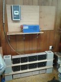
I already have my Inverter / charger and solar charger ( 48V system )
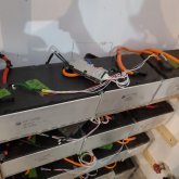
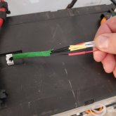
I just need to figure out how I'll balance the cells. This module came with all the control modules in the set.
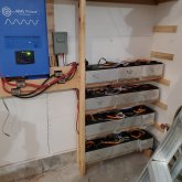
I have dismantled the module, removed all the batteries, they are in 3s, 4s & 5s packs and rated at about 26Kwh
And I need advice on what is the best way to keep em balanced. Does anyone know if the OEM balance modules can be reused in anyway?
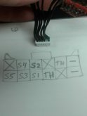
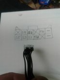
My 48v packs consist of the following..
1x 5s + 3x 3s = 2 sets
2x 4s + 2x 3s = 2 sets
2x 5s + 1x 4s = 2 sets
I have 3 left overs i can't make use out of yet. ( 1 of each 3s, 4s and 5s ) Future use maybe.

I may not have enough solar to charge them. I have about 1800W to 2000W of solar on my roof.
I have on order an AIMS 2kw inverter / charger and a 60A EPEVER MPPT charge controller.
I'm hoping to run a few isolated circuits in my house to offset my electric bill, things like the 2 refrigerators and the lights, maybe the tv.
if only just the fridges, that'll be a big help.

Thanks for reading.
 
So it looks like you have a 14s system? How many volts does each cell provide? Can they be broken down any further. Im not sure but from the way I am understanding your plan you would need 6 BMS
 
Yes, 14s6P 48V
but the issue is,, with such a large system, I'm not sure that a typical BMS can handle such a large battery..
I been reading up a lot, and some say you need a BMS, others say no, just check things out regularly. and manually balance if needed.
and choosing active balance vs passibe balance.. I am still trying to read up on that.
 
So it looks like you have a 14s system? How many volts does each cell provide? Can they be broken down any further. Im not sure but from the way I am understanding your plan you would need 6 BMS

I need 14s BMS, the batteries have separate cells that can be tapped..
Some of my terminology might be off.. I'll say a Pack, that can have either 3s 4s or 5s inside.
and by combining various pack, I achieve the 14s set up.
Just need to decide on what i'll use.
Either Daly or ANT BMS.. But the solar charger does the charge controlling, and the charger on the Inverter ( inverter / charger ) also is settable.
So maybe i just need me an active balancer only...Or ????
I have available 6 banks of 14s batteries, so i'll need a balancer or BMS for each bank..
 
From a single BMW Active-E pack

final(6):
554: 3
4433: 2
5333: 1
leftover 3s: 4
ah: 450
kWh: 21

If you can buy four(4) 4s you could get 2 more 48v combos (but they're sold out on batteryhookup):

with 4 more 4s you get:
final(8):
554: 3
4433: 4
5333: 1
ah: 600
kWh: 28


Another option:

final(6):
554: 2
4433: 1
5333: 3
leftover 4s: 3
ah: 450
kWh: 21

You CAN buy 2 additional 3s from batteryhookup (they have them in stock) and get:

with 2 more 3s, you get:
final(7):
554: 2
4433: 2
5333: 3
leftover 4s: 1
ah: 525
kWh: 25

AH are assuming there are 75ah available per combo. this is from looking at batteryhookups testing of the 3s and 4s cells:
1599067384426.png


For the BMS, the Daly 14s 100a is a good choice, but I'm going to keep the current down to maybe 50 initially until I can see how warm they get. These are SB LiMotive batteries (joint company of Bosch and Samsung SDI). If you get a BMS let us know how it works out - I'm just getting mine setup as well.
 
MelKier >> the info you posted, is this your set up ? or were you suggesting things to me ?
if you were, I don't quite follow it...
The batteries i have, I can't see the sticker on the actual cell, it looks covered up by the battery tabs.
But the batteries were bought from BHU. The page is gone now since they sold out, but they listed it as 96S pack,, 3 modules total.
COMPLETE BMW OEM 32kWh EV ACTIVE-E BATTERY 96S
 
Not really suggestions, but possible configurations

554: 3 <== means 3 packs of (2x5s + 1x4s)
4433: 4 <== means 4 packs (2x4s + 2x3s)
5333: 1 <== means 1 pack of (1x5 + 3x3s)

each "pack" is 48v and approx 75AH.

I have 2 of the same 96S battery packs from BHU.

I bought a single DALY 14s 48v 100A BMS and am checking it out now.
 
cool deal....
The left over cells i have , wondering if i should keep them or resell them,....
If i use all 6 strings i have, i should get 665Ah
 
I have this same pack hooked up to a 12kw inverter charger as a partial home backup. Unfortunately I started out with a 13s config so I'm running into high voltage during charging issues. They discharge just fine, I've been able to cycle them twice but had to manually stop the charging process.

I have 4 13s banks setup right now with a generic 60a bms I got off Ebay. My end goal is 6 14s banks with a 60a daly bms on each bank. Just ordered the Dalys so i can't comment on those but the generics are doing great.

A quick tip for hooking up your bms when you get it: there's a small white rectangular connector on top of each battery that is used for balancing and temperature monitoring. If you keep the old connectors that came attached, you can remove the unnecessary pins and solder the bms wires to them. Makes it easyish to connect your bms to the cells.
 
yes , i still have the connectors and all the BMS modules, but no idea how to utilize them....
it would be nice if the mapping of the pins matched all the batteries..
I do not know this yet, as I will have to bug out all the wires and see if they match up in an order.
example,, the 3s pattern matches the 1st 3 cells of the 5s..
Kind of like the 1s-8s battery meters do..
 
Actually they all do and I've already mapped them out.
***____***
[ o 4 2 . . i]
[ 5 3 1 . . i]
========
The o is the output voltage, i is input voltage. So on battery 1 in your bank i should be 0. Pin o on battery 1 will match pin i on battery 2. 2 of the other 4 pins are for an internal temperature sensor. I don't use them so I don't know which ones. This layout is the same for all of them, 3s 4s & 5s.
You can use the i pin on the first battery as your black lead and the o on the last battery as your positive lead.
 
I don't quite follow the diagram you made.
can you clarify a little bit ?
Below is my intended layout
Starting off with 2 strings (14s) can go up to 6s
 

Attachments

  • 20200726_134051.jpg
    20200726_134051.jpg
    115.5 KB · Views: 14
It's the pin layout of the white connector on top of the individual batteries. It's the same on every battery. Here's some pics of my setup. It's not complete but you get the idea of finished product. Fyi the spacing between the feet on the bottom of the battery is 5.5".

I soldered each bms wire to its corresponding pin on the original ev wiring harness. Not the actual pin mind you but the wires coming off them, that's why you see the original wrapping still.
Cut the connectors off of the harness, remove the unneeded pins, attached the bms wires to them and you have a simple way to connect eveything without needing to get into the innards of each battery. Be careful not to do this with the connectors connected to the battery, or accidentally short two pins measuring the voltage ?, it's not pretty.
 

Attachments

  • 20200907_210916.jpg
    20200907_210916.jpg
    80.7 KB · Views: 18
  • 20200907_210950.jpg
    20200907_210950.jpg
    70.4 KB · Views: 19
  • 15995351120727481421867941535631.jpg
    15995351120727481421867941535631.jpg
    49 KB · Views: 16
Oh the 5s batteries use pins 1-5, 4s use 1-4 with no voltage on #5, 3s use 1-3 with no voltage on 4 and 5. Eveything uses the input and output pins. What voltage you get from them depends on where they are in your battery series.
 
looking good.. looks like you have 2 5s and 1 4s on all 4 strings ?
I still wanna save the temperature wires, I might figure a way later on to use them..
How much solar are you using to charge the batteries ?
 
Update, I got it figured out. I see the pattern now..
I made a pencil drawing of battery view and made a quick tester.
Works great, i saved the wires of the thermal sensor just in case I can find a way to use em.
I just used 1 connector, it works for all 3 sizes
 

Attachments

  • 20200908_201920.jpg
    20200908_201920.jpg
    50.4 KB · Views: 15
  • 20200908_201738.jpg
    20200908_201738.jpg
    53.2 KB · Views: 13
  • 20200908_201525.jpg
    20200908_201525.jpg
    71.3 KB · Views: 11
  • 20200908_201509.jpg
    20200908_201509.jpg
    60 KB · Views: 8
  • 20200908_201406.jpg
    20200908_201406.jpg
    67.9 KB · Views: 7
Nice, good job there! Makes it easier because you can build your bms harnesses on your table then it's all plug and play. Mine are currently 2@ 5-5-3 and 2@ 5-4-4 for 13s but that doesn't fit the voltage range of my aims inverter charger. I've got some 14s bmss on the way but it will be a minute before they get here. I should have started ast 14s like you are.
 
ya, I'm still on the fence as to which BMS to choose.. it's so confusing..i've narrowed it down some, but the interface ( programming ) looks really confusing.
I need to order a surge arrestor for the solar as well, as they are mounted on my roof,,,and share a lightning rod system.
 
So far I like my JK BMS, it has been working perfectly, Even though it rarely needs to do any balancing, I really like how the active balance works. I probably would have paid the extra for a Batrium if it did active balance instead of just the resistor bleed off. Knowing how well my cells are matched and staying in balance, maybe the resistor bleed would have been fine, but I also didn't care for the protection just tripping a breaker and having to go to the pack to manually reset it. Not a bad to idea to have to go check why it had to shut off though.
 
I need to make a decision soon..lol
I'm still comparing things.. really don't need the wifi and communications options..would be nice if there was a nice one that had it's own dedicated display.. Maybe i'm looking for too much, this being my 1st big build and wanting all the safety i can get.
 
Back
Top