diy solar

diy solar

Need advice planning an RV solar system

Ranger Rick

Here comes the sun
Joined
Feb 23, 2022
Messages
96
Location
SW Idaho
I am a neophyte to RV solar systems. I’ve been using a Renogy 100w solar suitcase to charge lead acid RV batteries for 5 years. Now, I’ve purchased a used 2020 Grand Design 5th wheel that was used only full-time at a building site. It was on a 50amp service and propane.
I have one new REC N-Peak 2 370 watt panel from a residential job. VOC of 41.1v and also 10.7 amps. I also have two SOK 12v 100Ah LiFePO4 batteries.
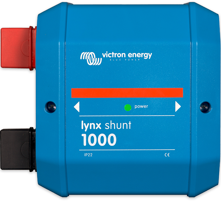
My initial plan is to run from the battery bank a VE SmartShunt negative line and a terminal 400amp positive 4/0 cables to a VE Lynx Distributor
Then use the Lynx to distribute lines to a Victron 100/50 Smart Solar Charge Controller, the RV's 12v distribution/converter box (checking lithium compatibility), and a DC to DC 20a charger from my truck. I will save the 4th Lynx line for a future 3k or 2k Inverter/Charger. I have never used high watt devices (microwave, air conditioners, Kuerig, in trailer camping the last 10+ years.

My questions are:
  1. What do you recommend for the battery end? Anchoring the Smart Shunt and T-fuse directly to the battery? Or, use a shunt bar? Or other?
  2. What fuses are recommended for inside the Lynx?
  3. When I do expand with an I/C, more batteries and another panel, how are higher watt PVs compatible with a 12/volt battery bank? I’ve seen some systems with 1,000+ watt solar panels while also seeing that there is a ~600w PV limit in 12v systems.
Thank you! RR
 
I am a neophyte to RV solar systems. I’ve been using a Renogy 100w solar suitcase to charge lead acid RV batteries for 5 years. Now, I’ve purchased a used 2020 Grand Design 5th wheel that was used only full-time at a building site. It was on a 50amp service and propane.
I have one new REC N-Peak 2 370 watt panel from a residential job. VOC of 41.1v and also 10.7 amps. I also have two SOK 12v 100Ah LiFePO4 batteries.
My initial plan is to run from the battery bank a VE SmartShunt negative line and a terminal 400amp positive 4/0 cables to a VE Lynx Distributor
Then use the Lynx to distribute lines to a Victron 100/50 Smart Solar Charge Controller, the RV's 12v distribution/converter box (checking lithium compatibility), and a DC to DC 20a charger from my truck.
Get an isolated dc to dc charger for this application.
This is >$400.00USD
This is <$200.00USD
I think you are asking about overall topology, if yes I would be glad to expand on that subject.
My questions are:
  1. What do you recommend for the battery end? Anchoring the Smart Shunt and T-fuse directly to the battery?
Class t is the safest choice.
MRBF is likely ok.
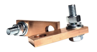
  1. Or, use a shunt bar?
What is a shunt bar?
  1. Or other?
Not clear what you are asking here.
  1. What fuses are recommended for inside the Lynx?
Lynx distributors use mega fuses.
  1. When I do expand with an I/C, more batteries and another panel, how are higher watt PVs compatible with a 12/volt battery bank?
A 2000 watt continous inverter/charger is ok at 12 volts.
3000 watt is doable but really pushing the limits.
I suggest going to 24 volts for > 2000 watts inverter.
Will also depend on your pure dc loads.
 
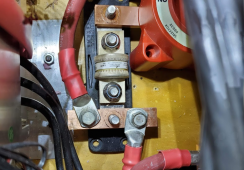
You have two batteries, so you can't attach the shunt or the fuse directly to the battery. You need to run cables from each battery to those devices. Be sure the cables are of equal length to ensure the batteries have equal access to the charge/load.

You can place a bus bar on the input end of each device, then attach the cables to the bus bar. The picture below is an example of my first attempt at doing that. The 3/4" wide bus bar was subsequently swapped out with a 1" wide bus bar that fit the fuse better (more surface contact) and the lugs fit better too (more surface contact).

1650036678193.png
 
Thank you. Yesterday I ordered 1/4" x 1" x 12" tinned copper bar the I will be making my bus bars :)
 
You have two batteries, so you can't attach the shunt or the fuse directly to the battery. You need to run cables from each battery to those devices. Be sure the cables are of equal length to ensure the batteries have equal access to the charge/load.

You can place a bus bar on the input end of each device, then attach the cables to the bus bar. The picture below is an example of my first attempt at doing that. The 3/4" wide bus bar was subsequently swapped out with a 1" wide bus bar that fit the fuse better (more surface contact) and the lugs fit better too (more surface contact).

View attachment 91333
Three questions HRTKD: What terminal fuse block are you using? What amperage T fuse? What are the two positive lines you have attached to your bus bar? Thank you ?
 
Back
Top