This is a possibility.
My guess is that you are connecting the chargers direct to the battery, thus bypassing the shunt. The shunt connects as shown on page 5 in the shunt instructions.
When I connected the two variable chargers, I used the main boat’s Main negative post and Main positive post, to avoid charging one of the batteries more than the others.
No negative connection , loads or chargers are connected to the battery negatives directly. With multiple 12v batteries in parallel the negative terminals are connected together, the shunt connects to this point and everything else to the other end of the shunt.
Hmmm, my last “Solar expert” who was Electrican number three working on this left 3-4 cables connected to the Main battery bank negative. (Which from your link to the Victron instructions, should only the Victron cable and that’s it…)
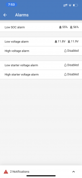
The low state of charge alarm is a setup issue or a installation/commissioning issue or both. The battery at 12.7 volts is (assuming no significant load or charge) at a high state of charge.
I’ve had these batteries installed like this for 6 weeks now. They usually rest at around 13.4v when fully charged. They have been off the charger for 8 hours now and they show 12.7v which was usually the 80% capacity point back when the Victron smart shunt was reporting things accurately.
Because the voltage on a lead acid battery changes with state of charge you can estimate roughly the state of charge knowing the voltage of a resting battery.
The chart on your link shows that 100% fully charged is 12.7v? However, these batteries are usually resting at around 13.4v when unplugged from the charger…
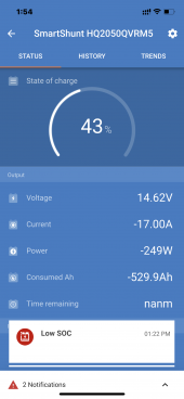
The display picture you posted indicates,
43%state of charge
Voltage 14.62 indicating its perhaps being charged, perhaps by solar.
A negative discharge of -17 amps, this seems odd as it does not corollate with the 14.62 volts.
-529.9 amp hours discharged, this seems unreal.
When I took that picture, the batteries were charging for 3 hours with two 10A variable voltage chargers set to 14.65v and two of 3 working solar controllers connected. (The amps came down to around 0.5A on both meaning they were almost fully charged.) However, the capacity never went up, even though the voltage went up??
The negative discharge Amps started at around -18A on the Victron Trends page and eventually made it (up) to -16.5A. The boat usually operates at a -12A draw for both the freezers that are hardwired in.
The -529A total discharge is a total number. Victron doesn’t say if that’s for 1 day, or an all time low?? I have no idea why Victron wouldn’t label that better
To help further details are required.
What batteries are installed, how many, what is the specified Ah, how old are the batteries?
There are 8 “Ever Ready” Marine Deep Cycle lead acid batteries installed in parallel. I bought them from Pricesmart (the Panamanian version of Costco) and they have no Amp Hour rating since Pricesmart relabeled them from whoever made it.
When I set the Victron up for the first time, I labeled them 100Ah each for a total of 800Ah. There is a possibility that they are up to 160Ah each but I doubt it. (There was a random 160 printed on the battery sticker with no explanation. I’ve tried calling Pricesmart but they said they wouldn’t tell me any more info.)
What solar controllers do you have, what panels, how are they connected to the batteries?
I have 3 Outback Flexmax solar controllers. One 60A and two 80A. One of the 80A controllers went bad at the same exact time the Victron started acting up so it could be related but I doubt it. I shut the breaker off for that 80A Outback controller that went bad.
They Flexmax controllers are connected directly to the battery bank main negative Battery#8) and main positive (Battery #1) on the batteries themselves.
Do you have a system diagram?
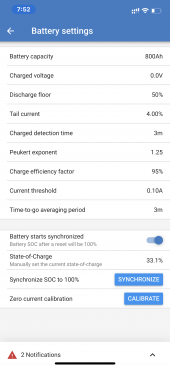
Can you post a picture of the settings page for the shunt?
No diagram. I’m in the process of requiring the entire boat because the previous owner made a nightmare mess of things trying to design some kind of dual 110/220 US/Euro system. So most of the things on the boat are just disconnected now until I can get my lithium batteries back in a few weeks from now when I finish testing them.
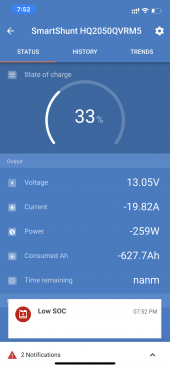
Ill attach more screenshots of the current capacity as well as the settings like you asked. Thanks!
Can you post picture of the connections between shunt , battery?
It’s in a hard place to take a picture. Maybe tomorrow.
Basically it goes like this:
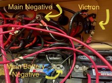
Main battery bank negative terminal (with a few negative cables attached directly to the battery, likely from the solar controllers) > 1’foot of 1/0 cable going to the mounted Victron 500A smart shunt > then another 1’ 1/0 cable connecting the Victron to the Boat’s main negative terminal (with a ton of other cables connected.)
Some of your statements are difficult to understand.
"I have lead acid batteries, if they get too low they stop working "
"One of my three solar controllers stopped working"
"5 hours in the sun not charging"
Sorry, I have a boat full of people trying to have fun while I’m doing all this asking me stupid questions constant. It’s hard to focus and be specific. Thanks so much. To clarify:
- I was told that Lead Acid batteries can’t go below 50% of their rates capacity like Lithium can which is why I said I don’t want them going too low. The Victron was reporting 50% capacity so I was freaking out. Since then even after charging them for three hours the reported capacity hasn’t gone up at all.
- Before I went to bed last night, I checked the Victron app and it said 70% capacity. So I was worried and wanted to see if the batteries were charging by 10am. That’s when I found that one of the three Outback controllers were not working correctly. I called Outback and they vereidig it’s bad and will send me a new one.
- By the time I posted this, the sun was up for 5 hours. But the voltage and the capacity didn’t go up at all. Which still makes me worry that the other two working Outback solar controllers are not fully up to the task of charging these batteries in the future.
The issue with "not charging" could be as simple as a failed fuse/ breaker trip/ loose wire.
Until there is more information its guesswork.
All the wires are solidly connected and tightened on with bolts. I made sure of that and checked again.
Does your system have the shunt and solar chargers connected by a communication buss?
Do you have a low battery protect?
No communication bus that im aware of. I listed the way everything is connected above.
General advice on boat electrical systems.
You must attempt become proficient in fault-finding the electrical system. Read all the installation manuals on the various system parts. Study the wiring diagram of the boat system and familiarise yourself with testing and changing fuses or reseting dc breakers.
Read material on lead aid batteries and how to care for .
Mike
Yup, hey thanks. Yeah im usually decent with electrical issues but this boat is a nightmare because it’s a French boat with no actual wiring diagrams. And the manual is useless. The previous owner was an idiot who did everything half ass and not the correct way even if he meant well. And I have no previous experience with solar and lithium so the last 3 months has been a learning curve. I also have had 3 different electricians on board who all give conflicting advice with each other. So I really appreciate your help and everyone else here. It’s been a lifesaver.
Here are the pics you requested: