diy solar

diy solar

Need help to power RV DC and GFCI outlets only.

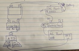
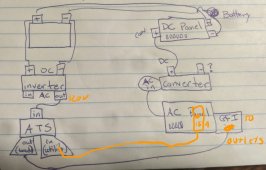
Thanks for your response. I drew a diagram of what I think you're suggesting. Can you take a look and tell me if that's right?

A couple additional questions
  • How does the ATS stop power from coming from the batteries when I'm hooked to shore power. I thought the shore power needed to run through the ATS to cause it to switch. I suppose power might be coming back from the GFI line... is that it?
  • Do the inverter AC-in or the converter negative (assuming that exists) need to connect to anything?
I don't see a diagram. Still in progress?

There are two inputs to the ATS. One input is from the branch circuit breaker. When shore power is available the transfer switch will pass through the shore power. The second input is from the inverter. If there is no shore power the inverter power will feed to the single branch circuit.

OK so an ATS has a normally closed side and I would connect that to the inverter. The normally open side Goes to the branch circuit breaker. The relay will then switch when shore power is present and disconnect the inverter. The normally open side is often called the generator side. Or of course you can just turn the inverter off.

There is no inverter in for what I describe. If the inverter has an in & out then it has an internal transfer switch. This can work also but these are often larger inverters. My description is primarily for a smaller stand alone inverter. The existing converter can continue to be used to charge the battery.
Oops, I forgot to attach the diagramPXL_20210611_225950703~2.jpg
 
Need to feed the ATS-IN from the AC PANEL.

The GFI can be moved away from the AC PANEL as it will get power from the ATS only.
 
The drawing shows and inverter with in and out, that means it is an inverter charger with a built in automatic transfer switch.
The discrete transfer switch is not required.
You asked earlier how the ATS effects charging, When you are on shore power the batteries are charged by the inverter charger and the ac loads are passed through to the pedestal.
When shore power goes away the batteries automatically pick up the load and charging stops.
With a decent inverter charger you won't even see the lights flicker when it switches over.

A discrete ATS can take >100ms to switch.
An inverter charger generally takes <20ms.
 
Need to feed the ATS-IN from the AC PANEL.

The GFI can be moved away from the AC PANEL as it will get power from the ATS only.
Awesome, this is all starting to make sense! I'm going to take another stab at a diagram tomorrow and then maybe I can finally order gear.
 
The drawing shows and inverter with in and out, that means it is an inverter charger with a built in automatic transfer switch.
The discrete transfer switch is not required.
You asked earlier how the ATS effects charging, When you are on shore power the batteries are charged by the inverter charger and the ac loads are passed through to the pedestal.
When shore power goes away the batteries automatically pick up the load and charging stops.
With a decent inverter charger you won't even see the lights flicker when it switches over.

A discrete ATS can take >100ms to switch.
An inverter charger generally takes <20ms.
With my drawing and an inverter /charger, wouldn't that create a loop with the existing power converter? The inverter and discrete switch avoid that loop
 
With my drawing and an inverter /charger, wouldn't that create a loop with the existing power converter? The inverter and discrete switch avoid that loop
Your drawing doesn't represent anything that you should actually implement.
As I said before the simple thing to do is just turn off the converter breaker.
The converter function is handled by the inverter charger.
 
If the inverter has an IN and OUT for 120v power then you do not need a separate transfer switch. If this is the case you connect the branch circuit Romex to the OUT and wire the Branch circuit breaker to the IN.
 
What inverter are you looking at?
What do you plan to run on inverter/battery power?
Just trying to figure out what gear I need before I finalize. I've been looking at 1000w inverter /chargers, but only because that's what I thought I needed.

I want to power everything going through the DC panel and the GFI outlets
 
If the inverter has an IN and OUT for 120v power then you do not need a separate transfer switch. If this is the case you connect the branch circuit Romex to the OUT and wire the Branch circuit breaker to the IN.

If the inverter has an IN and OUT for 120v power then you do not need a separate transfer switch. If this is the case you connect the branch circuit Romex to the OUT and wire the Branch circuit breaker to the IN.
OK, gotcha. Thanks for taking the time to respond so promptly.
 
I use the GoPower 300 watt for these small items. GP-SW300-12
Has low idle draw and a provision for a remote power switch.

The small size allows you to draw 12v power direct from the existing 12v main connection to the battery(usually). With a large inverter (1000w+) you are probably looking at pulling wire to the battery. Of course if access is easy there is no concern.

I'm definitely down to run some wire, and I will probably go for a larger inverter in case I decide to upgrade my system to run a little bit larger stuff.
 
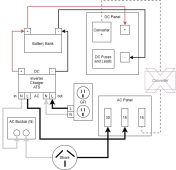
OK, here's what I've come up with, thanks to all of your help. Please correct anything that's wrong. Note I dont include any of the grounds, which I understand need to be connected to the ground for the unit, nor am I showing power coming in from the charge controller. Also, I show the existing power converter, but I would flip its breaker to remain OFF at all times.

What about in-line fuses? I have been told I should put a fuse between the inverter/charger/ATS and battery bank. Anywhere else that is recommended?

Solar.png
 
@AustinMilt Pretty sure this is what @GSXR1000 was describing.
As you have no free ac branch circuit breakers the converter is disconnected and its breaker is reassigned to the inverter_charger
Code:
ac {
    pedestal->inlet->surge_protector->30A_master_breaker->15A_branch_breaker->inverter_charger->GFCI_outlet
}
dc {
    pos {
        |<->battery.pos
        |<->inverter_charger.pos
        |->dc_panel.pos
    }
    neg {
        |<->battery.neg
        |<->inverter_charger.neg
        |<-dc_panel.neg
        |<->inverter_charger.eq
        |<->chassis_bond
    }
}
 
Back
Top