diy solar

diy solar

Need help with A/C Neutral and Ground w/Growatt inverter...

jsl10

New Member
Joined
Jan 26, 2022
Messages
50
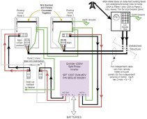
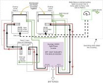
I'm working on my new solar build using a Growatt 12kW split-phase inverter from Sig. Solar. Trying to make sure I'm doing the grounding correctly to avoid ground loops. Please see attached image of what I have. Essentially, it's two home service panels (independent panels since each gets fed it's own service line from the meter base on another building). Panel 1 feeds A/C into the inverter and Panel 2 accepts A/C from the inverter via it's back-feed generator breaker (has safety lockout plate to make sure main is off when gen. breaker is on). The A/C output of the inverter runs to a backfeed breaker in a new small breaker panel where solar loads will be distributed (to home Panel 1 during power outage and E-Car charger 24x7).

I was thinking since Panel 3 doesn't bond N to G it would be ok. But now thinking that since N is bonded to ground in Panel 2 it might feed a ground back to the inverter via N (NOTE: when panel 2's main is switched OFF, N is still connected which is bonded to G - hope that makes sense). Also read that some Growatt inverters manage the G/N bonding internally now. I understand the one N/G bonding location rule but I've got two essentially independent panels each with N/G bonded with the inverter siting between them. Anyway, I've read some of the grounding documents here and still very confusing! Thanks in advance for looking this over and giving me feedback!
 

Attachments

  • A_C wiring.jpg
    A_C wiring.jpg
    93.4 KB · Views: 136
Hmmm. Interesting layout. It took me a while to get my head around all the implications.
1643237759701.png

1) The wiring of the equipment grounding wire looks correct.
2) I assume there is no ground from the meter to the Existing Home Panel 1 & 2. If so, having an N-G bond in each of those boxes seems wrong.
3) Are there loads powered by Panel 3?
4) Do you know if the SPF 1200T DVM does automatic NG bonding?: The reason is that when it turns the bond on it would be a 2nd bond. (The loads would 'see' both the Inverter bond and the bond in Panel 2.) This would create an inappropriate current on the ground from box2, through box1 and back to the bond in the inverter. To fix this, either the Growatt has to be modified to not do a bond -or- the Neutral needs to be switched along with the two hots on the Generator Lockout. Can you do a 3 pole generator lockout?.... Probably not. You may have pull that function out to a dedicated 3 pole transfer switch)

EDIT: Added following sentence

Note that the solution to this impacted by the solution to item 5 below

Note: Growatt recently made changes around the bonding on their 3K inverters. I do no know off hand what the SPF 1200T does and if they have made any changes recently.

5) When the inverter is in pass through mode, the loads will 'see' both the N-G bond in box 2 and the N-G bond in box 1. This will create an inappropriate current on the ground between the two boxes. The only way I can think of to fix this is to switch the neutral where you have the generator lockout. (3 pole transfer switch)

6) When the inverter is in transfer mode, there is a big loop in the neutral: From the meter to box1, to the inverter, to box2 back to the meeter. This can cause RFI problems just like a ground loop. (Neutral loops are not common so you don't hear about them much....but they can be just as problematic). The good news is that when you fix item 5, it will fix this as well.


EDIT: Added following sentence

When a transfer switch is added, the inverter needs to provide the N-G bond.
 
Last edited:
Thanks FilterGuy for the detailed reply! I know it takes time and I really appreciate it. I'll have to read it a few dozen times to absorb it! :) Anyway, wanted to address some of your questions and points...

1) That's good!

2) There actually are grounds that run to the meter. Each panel has a four cables coming in (H+H+N+G). These two sets of 4 cables run about 100' to another building where the meter base is. So given that, I assume the N-G bond in the two panels is ok? This is how the electricians did it when they built the house 5 years ago and it was of course inspected so hoping it's correct!

3) I was going to put a 240V 20A breaker in that would feed a 240V 20A receptacle for the car charger. This load could be used at any time (not like panel 2 which would only be a load when switched over during an outage).

4) I looked through the manual on the SPF 1200T DVM and it says nothing about it. I'll check with Sig. Solar and let you know.

4 & 5) So you would switch the Neutral line so it's broken when not back-feeding to panel 2? So when it is back-feeding to panel 2 the Neutral is ok the way it is? Still confused on this point.

Your last point on inverter needing N-G bond if 3-pole transfer switch used... Would that be N-G bonding only on the IN or would that include the N on the OUT as well?

Until I hear back from Sig. Solar, I'll assume the inverter does the bonding for now. I'll update the drawing to show what I THINK you are meaning. Thanks again for helping with this!
 
Thanks FilterGuy for the detailed reply! I know it takes time and I really appreciate it. I'll have to read it a few dozen times to absorb it! :) Anyway, wanted to address some of your questions and points...

1) That's good!

2) There actually are grounds that run to the meter. Each panel has a four cables coming in (H+H+N+G). These two sets of 4 cables run about 100' to another building where the meter base is. So given that, I assume the N-G bond in the two panels is ok? This is how the electricians did it when they built the house 5 years ago and it was of course inspected so hoping it's correct!

No, you need to determine if N-G bond exist at meter. On my acreage, power comes into the meter socket which runs to a main panel mounted right at the pole. N-G bond takes place there with that main panel. Each building then is fed thru a breaker from that panel and no bonding at any main panels (which really are subpanels). A ground wire is run to each building along with the 2 L's and N.

This was installed by my cousin who was a licensed electrician and inspected by the state electrical inspector. Power company would not install a meter until it was all inspected and passed.

Considering they ran 2 L's, and N and G to each panel, I would almost think the N-G bond is at the main point of service.

3) I was going to put a 240V 20A breaker in that would feed a 240V 20A receptacle for the car charger. This load could be used at any time (not like panel 2 which would only be a load when switched over during an outage).

4) I looked through the manual on the SPF 1200T DVM and it says nothing about it. I'll check with Sig. Solar and let you know.

4 & 5) So you would switch the Neutral line so it's broken when not back-feeding to panel 2? So when it is back-feeding to panel 2 the Neutral is ok the way it is? Still confused on this point.

Neutrals are never to be switched or have a breaker.

Your last point on inverter needing N-G bond if 3-pole transfer switch used... Would that be N-G bonding only on the IN or would that include the N on the OUT as well?

Figure out where the N-G bond is first.
Until I hear back from Sig. Solar, I'll assume the inverter does the bonding for now. I'll update the drawing to show what I THINK you are meaning. Thanks again for helping with this!
When the inverter is running and no bypass from grid is occurring, the unit will bond N-G at the inverter because it is the source.
 
2) There actually are grounds that run to the meter. Each panel has a four cables coming in (H+H+N+G). These two sets of 4 cables run about 100' to another building where the meter base is. So given that, I assume the N-G bond in the two panels is ok? This is how the electricians did it when they built the house 5 years ago and it was of course inspected so hoping it's correct!
Wow! That really surprises me!!! That means there are two N-G bonds and that ain't right!!! Throw a clamp meter on one of the grounds between the meter and a box. You will probably find a current on it that is about equal to the corresponding neutral.

Typically, the N-G bond and the earth-ground connection is at the service entrance....and that would be where your meter is. However, you clearly you have something different. (This is one of the reasons it took me a while to grock the drawing.... it is different than I am used to.)

If there is an earth ground at the meter, there probably should not be an earth ground at box one.

BTW: Some inspectors really know their stuff and pay close attention. Others......welllll.....not so much.

4) I looked through the manual on the SPF 1200T DVM and it says nothing about it. I'll check with Sig. Solar and let you know.
Growatt is horrible at documenting the grounding and bonding scheme on their inverters. What is worse, it is different between the old versions of their 3K inverters and the new version but they have the same model number. It borders on criminal negligence.

4 & 5) So you would switch the Neutral line so it's broken when not back-feeding to panel 2? So when it is back-feeding to panel 2 the Neutral is ok the way it is? Still confused on this point.

Yes. Since the inverter will be providing the N-G bond, the Grid NG bond needs to be taken out of the circuit by switching the NG bond. I do not think that is possible with generator lock-outs......but I can not say that for sure. You will probably have to have a 3 pole transfer switch like this:


1643246593763.png

Also, notice some of the other changes I made:

1) Only one earth ground
2) Box 1 ground to box 2 ground jumper removed. (Otherwise there is a big ground loop through the grounds to the meter.
3) Removed NG-bond from box 2.
4) Added note that the NG bond should be in box 1 or at the meter but not both. (Preferably at the meter.)
 
Ok Zwy, your really making this interesting now! I looked up subpanel N-G bonding and in my first look I found this: "Starting with the 2008 National Electric Code, the only acceptable way to wire a subpanel is with a four-wire feed. Two hots, one ground, and one neutral wire. The grounds and neutrals must be isolated.". Our house was built after 2008! So your right assuming the house's two panels are "sub-panels". It makes sense that they are... on a detached shop, we have a 400A meter base. That meter base has one 200A connection that runs 4 cables to panel 1. The meter also has a built-in breaker panel that has a 125A breaker that runs 4 cables to panel 2. Would what I described be "sub-panels"? As you suggest, I'm going to open up the meter base and take a peak inside to see if they are bonded there. Here is Panel 1's and Panel 2's feeds and bonding: IMG_20220126_170741949.jpgIMG_20220126_170752120.jpgIMG_20220126_170832171.jpgIMG_20220126_170844830.jpg
 
These two sets of 4 cables run about 100' to another building where the meter base is. So given that, I assume the N-G bond in the two panels is ok?
Oh!! I did not catch that before. (Ignore my above diagram for now) Since the lines are coming from a separate structure it changes things but now the rules get difficult to navigate and (in my opinion) don't always make sense.

* Is the other building on the same meter as yours or is it separate?
* Are both feeders going to your house on the same meeter (I assume so, but want to be sure)
* Is the earth ground before the meter or after. (Believe it or not, this can change what is 'supposed' to happen.
Thanks for the drawing but ya, the meter (there is only one) is on a detached building. From the meter (400A), two sets of four cables are run to the two panels in the house. I'll check on where the meter's earth ground is when I open it up. I'm really curious to see what was done out there. IF... the N-G bond is done out there, it sounds like I could just remove the two bonds in the home panels. IF... the N-G bond is not done out there maybe it should be to meet current code. But your right, the code quote I did above did not reference if it is in a different structure. And that might change things regarding where bonding is done. Ugh.
 
Thanks for the drawing but ya, the meter (there is only one) is on a detached building. From the meter (400A), two sets of four cables are run to the two panels in the house. I'll check on where the meter's earth ground is when I open it up. I'm really curious to see what was done out there. IF... the N-G bond is done out there, it sounds like I could just remove the two bonds in the home panels. IF... the N-G bond is not done out there maybe it should be to meet current code. But your right, the code quote I did above did not reference if it is in a different structure. And that might change things regarding where bonding is done. Ugh.
Is it a single meter for both buildings? If so, that is the service entrance. There is supposed to be an N-G bond and a grounding electrode at the service entrance. Furthermore, the wires going to your building would be considered a feeder circuit.

A feeder circuit going to a separate structure from where the service entrance *is* supposed to be grounding conductor like your original drawing showed. What is interesting is that you have two feeder circuits and I guess they both have to be grounded. The wire between the two boxes accomplishes that but it also creates a ground loop..... so you are kinda stuck with being to code or having a ground loop. :unsure:

BTW: Do you have any idea why they ran two separate readers instead of one larger one?

The SPF 12000T DVM does not have a N input.
Good catch. The manual shows this.
1643254946054.png

It kinda implies you can do 240 *or* 120, but it is advertised as split-phase so I assume you can do both. (I hate Growatt manuals with a passion).
Since there is no neutral input on the inverter, there is no loop on the neutral and that simplifies things a little.

The fact that there is no neutral input makes me wonder if the inverter does anything at all for an n-g bond..... I am now guessing it does not. Of course, the manual does not say. (Did I mention how much I hate the Growatt documentation?)

The following diagram assumes:
1) There is an N-G bond at the meter
2) Box1 and Box2 are considered sub panels on feeders to a separate structure and must be earth grounded
3) The inverter does not generate an NG bond.
1643255349409.png


The next diagram assumes:
1) There is an N-G bond at the meter
2) Box1 and Box2 are considered sub panels on feeders to a separate structure and must be earth grounded
3) The inverter does generate an NG bond. (3 pole transfer switch)
1643254850423.png


In *both* of the above diagrams there is a big ground loop from the meter, to box 1, then to box 2 and finally back to the meter. Unfortunately, I am not sure anything can be done about it. (I am assuming the loads are too big to abandon one of the feeders)
 
The SPF 12000T DVM does not have a N input.
That feed wire on the right looks burnt and the allen screw not snugged.

Your right, my mistake on the drawing. I'll fix that. Thank you. I'll check the screw.

Re: WYTreasure... I'll check the screw. Thank you.

Also, the "burnt" look is anti-oxidant that is put on the aluminum conductors. They were kinda sloppy when applying it.
 
Is it a single meter for both buildings? If so, that is the service entrance. There is supposed to be an N-G bond and a grounding electrode at the service entrance. Furthermore, the wires going to your building would be considered a feeder circuit.

A feeder circuit going to a separate structure from where the service entrance *is* supposed to be grounding conductor like your original drawing showed. What is interesting is that you have two feeder circuits and I guess they both have to be grounded. The wire between the two boxes accomplishes that but it also creates a ground loop..... so you are kinda stuck with being to code or having a ground loop. :unsure:

BTW: Do you have any idea why they ran two separate readers instead of one larger one?


Good catch. The manual shows this.


It kinda implies you can do 240 *or* 120, but it is advertised as split-phase so I assume you can do both. (I hate Growatt manuals with a passion).
Since there is no neutral input on the inverter, there is no loop on the neutral and that simplifies things a little.

The fact that there is no neutral input makes me wonder if the inverter does anything at all for an n-g bond..... I am now guessing it does not. Of course, the manual does not say. (Did I mention how much I hate the Growatt documentation?)

The following diagram assumes:
1) There is an N-G bond at the meter
2) Box1 and Box2 are considered sub panels on feeders to a separate structure and must be earth grounded
3) The inverter does not generate an NG bond.


The next diagram assumes:
1) There is an N-G bond at the meter
2) Box1 and Box2 are considered sub panels on feeders to a separate structure and must be earth grounded
3) The inverter does generate an NG bond. (3 pole transfer switch)


In *both* of the above diagrams there is a big ground loop from the meter, to box 1, then to box 2 and finally back to the meter. Unfortunately, I am not sure anything can be done about it. (I am assuming the loads are too big to abandon one of the feeders)

Thank you so much for updated drawings! Very much appreciated.
To answer your questions:

Yes, it's a single meter for both buildings Why two feeders? I don't know. I know that a single 200A service wasn't enough so they wanted a second panel. It was probably cheaper but I really don't know. I apologize for having that N on the Input. Your right, that should simplify things and probably makes any talk of bonding of N-G within the inverter mute. But I'll find out from Sig. Solar. I noticed how the documentation only shows 240V -or- 120V! But since it's sold as a split-phase inverter I'm sure you can do both. On-line videos show using both the output N and BOTH 120 legs. I agree... documentation could use some work!!! Anyway, it's late and I need to re-read a few times your post above as well as check the bonding in the meter. I'll let you know what I find out.
 
Ok... here is what I have found out.

1 - I opened up the outside meter base on the detached building and the N-G are bonded there as well. Which makes sense since it has it's own local service panel as well. The bonding looks like it's a permanent part of the meter base (see first attached image at bottom).

2 - I spoke with Signature Solar's Master Electrician and he went over my plan and discussed three primary points:

First, he said it was correct to have the home's service panels bonded because the primary service feed (the meter) is on a detached building with no metallic conductor (other than the service feeds) between them. Since both panels 1 and panels 2 are fed independently and deliver their local circuits independently, it was correct that both are N-G bonded. Also, should be grounded at both ends as it is. Looking it up on-line as well, it dos seem that detached structure sub-panels are to have N-G bonded. So it sounds to me like the electricians did it correctly.

Second, he said there is no N-G bonding taking place inside the Growatt inverter. At least for my model that does not have a N on the input.

Third, there could be a ground loop between the house panels and remote meter but there really isn't anything reasonable to do about it. Because of the distance (about 100' of cable distance) and earths poor conductivity, this should be of minimum concern.

I updated my drawing to make things clearer (see attached). Thoughts? Does this all sound correct now?
 

Attachments

  • Meter.jpg
    Meter.jpg
    116.1 KB · Views: 54
  • A_C wiring.jpg
    A_C wiring.jpg
    101.1 KB · Views: 70
That is not correct. The neutral must be switched when switching between two independently derived power sources.
Well, there is fine line there, and not quite what I'm referring to. I'm referring after the main service panel. If I generator transfer switch is installed before the main panel, then yes. If installing a sub panel for critical loads with a generator or solar inverter, then a transfer switch should be installed and neutral switched. But other than that, no. Of course the reason why is there would not be a return path on an unbalanced load.
 
Ok... here is what I have found out.

1 - I opened up the outside meter base on the detached building and the N-G are bonded there as well. Which makes sense since it has it's own local service panel as well. The bonding looks like it's a permanent part of the meter base (see first attached image at bottom).

2 - I spoke with Signature Solar's Master Electrician and he went over my plan and discussed three primary points:

First, he said it was correct to have the home's service panels bonded because the primary service feed (the meter) is on a detached building with no metallic conductor (other than the service feeds) between them. Since both panels 1 and panels 2 are fed independently and deliver their local circuits independently, it was correct that both are N-G bonded. Also, should be grounded at both ends as it is. Looking it up on-line as well, it dos seem that detached structure sub-panels are to have N-G bonded. So it sounds to me like the electricians did it correctly.

Second, he said there is no N-G bonding taking place inside the Growatt inverter. At least for my model that does not have a N on the input.

Third, there could be a ground loop between the house panels and remote meter but there really isn't anything reasonable to do about it. Because of the distance (about 100' of cable distance) and earths poor conductivity, this should be of minimum concern.

I updated my drawing to make things clearer (see attached). Thoughts? Does this all sound correct now?
It would depend on your location but my system has one N-G bond at the service panel with grounds running to each building and there is not a N-G bond in each buildings subpanels. Some jurisdications didn't update the codes right away or the inspector or electrician was not updated.

I asked my cousin about how he wired this back then, this is his response," Only bonding should be at the first over current device. After that everything should be a 4 wire system with separate neutral and ground wires".

That is the way it should be wired. There is a main service panel at the meter location and that has a main disconnect and each building then has a breaker. That is how this place is wired and passed State Inspector. This was after 2008, about 2010 when it was wired all new and new buildings went up.

Now for the shop, in addition to that grounding, there is a Ufer ground, also known as a concrete encased grounding electrode that is connected to the ground bar in the shop. That "subpanel" is not N-G bonded. The grounding conductor runs from the service panel at the pole to the subpanel. My house and cold storage shed also have a grounding conductor run to their respective subpanels, those panels again are not N-G bonded. This is the way it should be. Now, I recall Mike Holt talking about additional grounding electrodes at other locations, basically at a subpanel that is not N-G bonded and he stated the additional grounding electrode serves no purpose. It isn't required, nor is it prohibited.

If you have N-G bond only at the main service panel and a 4 wire system to each "subpanel" then it is wired correctly. If you have N-G bond at any of the "subpanels", then it is wired incorrectly. Only 1 N-G bonding location after the service transformer.
 
This separate ground rod issue is a 2 fold thing.
1. Current "running" between the 2 grounds either due to "load" conditions ( yes not suppose to be a thing but as discussed it is) or a fault.
2. Spikes from lightning strikes.
Ultimately it is best to have only 1 ground rod, but if you need more they should ALL BE CONNECTED with very stout copper wire.
 
Third, there could be a ground loop between the house panels and remote meter but there really isn't anything reasonable to do about it. Because of the distance (about 100' of cable distance) and earths poor conductivity, this should be of minimum concern.
I agree the loop is probably inevitable, but the conductivity of earth has nothing to do with the loop. That part of his statement is nonsense.


I am struggling to understand what I am seeing in the photo.

1643313297028.png
Edited to clarify my questions.
A) A 200A 2-pole breaker that is independent of the rest of the panel (This is unusual to see but is probably the only way they could do the additional circuit without changing out the whole box. Some inspectors don't like this.)
B) The 200A 2-pole Main Breaker for the panel
C) A 2-pole ??A Breaker on the main panel. (I can not see the amperage, but based on the wire size it must be large.)
D) 240V feed from the Utility (Where is the associated Neutral from the utility?)
E) 240V Feed from the Utility. (Where is the associated Neutral from the utility?)
F) Unused heavy gauge wire pair
G) ??? 240V Feeder from breaker C. Where does this go???? (Where is the associated Neutral and ground?)
H) ???Connection to the Ground bar. (Is that the Neutral from the utility?)
I) ??? Wire from ground bar. Where does this go??? (The white band marking on it indicates it is a neutral. Is this the neutral for circuit G?)
J) ?? Feeder from Breaker A. Where does this go?? (Where is the associated Neutral and ground?)
K) 20A?? single-pole Breaker (I am guessing 20 due to wire size)
L) 30A?? dual pole breaker (I am guessing 30A due to wire size)
M) ??240V 30A? Circuit from breaker L with Neutral and ground. Where does this go? (That looks like 10AWG, but my eyes are not very well calibrated)
N) ??120V 15A? Circuit from Breaker K with the ground and neutral. Where does this go? (That looks like 14AWG.....)

I am trying to figure out what wires are going to the other building, and for each of the two circuits, where are the Neutral and Ground?
Also, as a curiosity, what feeds the building the box is attached to.
 
Last edited:
Back
Top